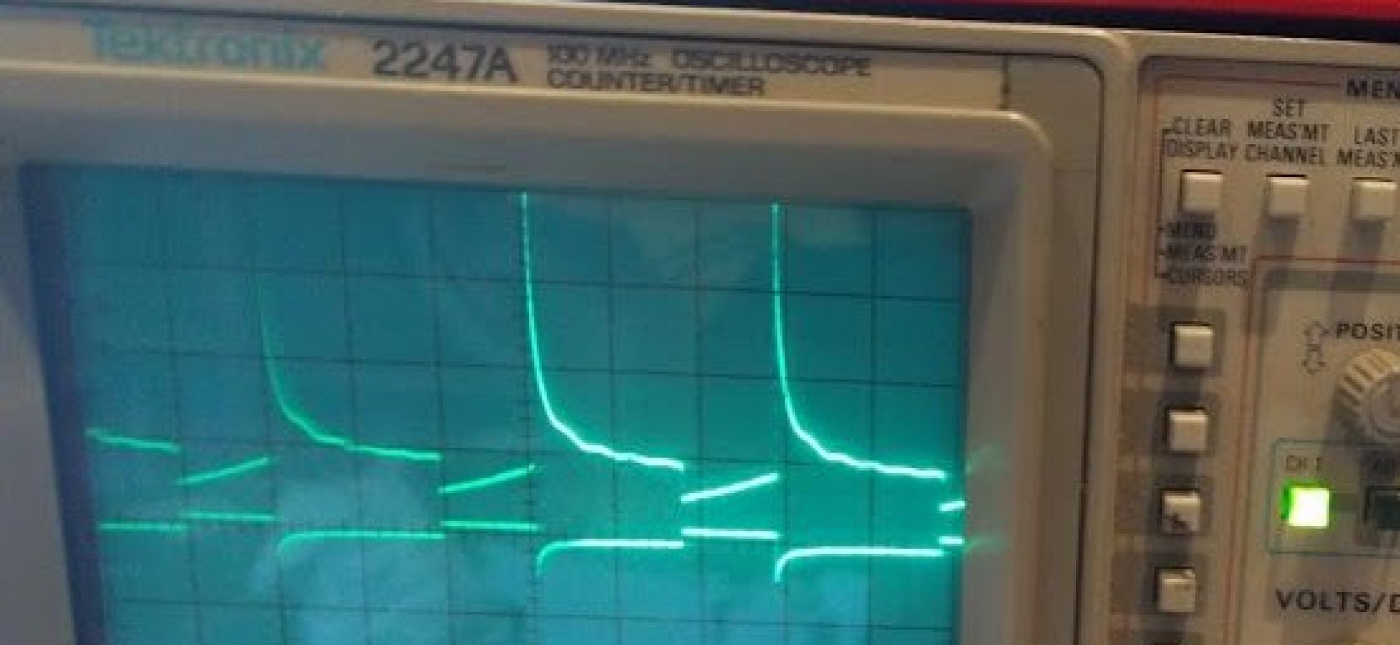
Finally, I am picking up my long delayed circuit simulator. It’s been almost a year, so it is long overdue. There is no better time to do pointless educational programming projects than while vacationing. If you want to have a quick view of where we have gotten, see the youtube video at the bottom!
Anyways, in the part I we laid out the math for basic linear passives. In part II we made some of the UI for schematic capture. In this part we will advance the UI considerably. Below is a description of more problems we had to solve.
Adding components and adding wires
We now allow adding wires by clicking and dragging and we have a palette of components that can be added on demand. This was fairly uneventful. We also added “Backspace” and “r” as key options to delete and rotate the highlighted component.

Managing connections
Allowing users to connect components is probably the trickiest part of the UI. The basic idea I came up with is to always assume we are on a grid. Every pin will always lay on exactly aligned to the grid. If two components pins are on top of each other then they are considered connected. Let’s get into the implementation.
To do this, we need a data structure that can map from a location to which component(s) (or at least how many) are incident at the location. A major design constraint is that we want it to be sparse, that is we don’t want a dense array of the grid nodes, so we actually implement this as a hash table. For simplicity we just consider the key of the hash table to be the string xCoord+”,”+yCoord (so it is human readable). Probably it would be more efficient to do some bit fiddly stuff like ((x&0xffff)<<16)+(y &0xffff), but we are just making something simple, so I’m going to punt on that aspect of performance.
Each UI operation will call functions on every editable component called buildNet(recordNet,unionNet). recordNet and unionNet are functions that the component can call to record any pin’s grid coordinates and unionNet let’s the component consider two grid coordinates to be connected (i.e. a wire uses these). For a resistor the buildNet() function looks like this:
ResistorSymbol.prototype.buildNet=function(recordNet,unionNet)
{
   var n1=recordNet(this.objectToWorld(0,0));
   var n2=recordNet(this.objectToWorld(10,0));
   return ["R",[n1,n2],this.value];
}
This registers the two pins of the resistor and returns a full description of the resistor for the net list (more on that later). The WireSymbol not only registers new nodes but also unions the two nodes into one conceptual node:
WireSymbol.prototype.buildNet=function(netRecord,unionNet){
   var n0 = netRecord(
             this.objectToWorld(this.points[0][0],this.points[0][1]));
   var n1 = netRecord(
             this.objectToWorld(this.points[1][0],this.points[1][1]));
   unionNet(n0,n1);
}
What does netRecord do? Basically it makes grid location based name and puts it into a hash table with the key being the name and the value being [<xcoord>,<ycoord>,<numberOfComponentPinsIncident>,<parentSet>]. xcoord and ycoord are obvious, <numbertOfComponentPinsIncident> allows us to draw an open circle when there is 1 unconnected pin, and a solid circle when everything is connected. Each component pin that touches this grid node increments that value. Lastly, parentSet is the name of the parent set in which we are contained. This will be explained below in the union set finding. The result of the buildNet() function is we have a data structure the UI can query when it is drawing to make open or closed circles at the pin locations.
Creating the net list
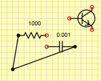
Given a schematic, we would like to create a net list which is a description of what the components are and how they are connected. This is different than the schematic which has extraneous spatial information. For simulation we want a distilled description with only bare essentials needed for the simulator. In basic circuit analysis we use the lumped element model where any wire connections are assumed to be ideal. That means that any pins connected by wires become a single node. To accomplish this, we need to track connected components, so we will use a disjoint forest tree algorithm. For simplicity I am going to omit using the rank heuristic, but that would be easy to add to get the coveted inverse Ackermann function big-O performance. Remember the <parentSet> item in the node hash table discussed above. We start that equal to the key in the hash table. This means that the node is its own parent. Since everybody starts that way, everybody starts as a set of 1. Any unioning will change one of the parent entries to be the other. This implies trees and we can always find the effective name of the set by following parent links from a given node. To see this in action, consider this circuit where no unioning has been done:
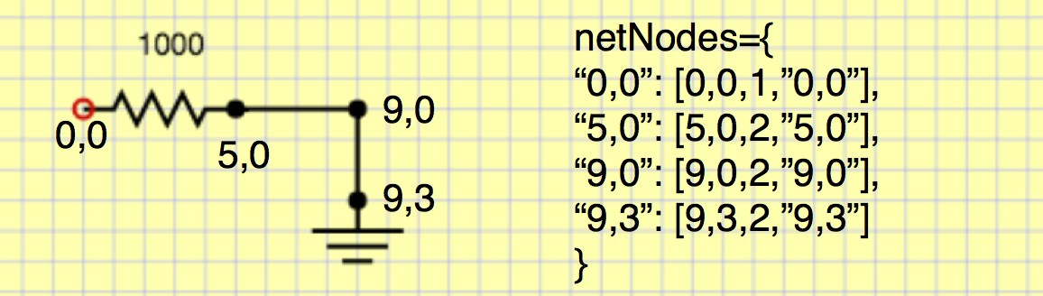
If we union one of the wire’s two pins we get:
If we union the other wire we get: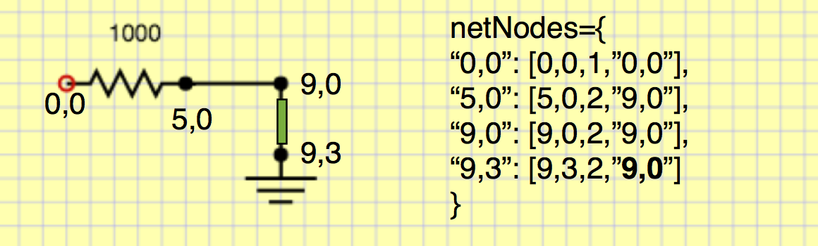
This is all good and find, but we actually need to handle GND specially.Anything that unions with GND gets parent being GND. GND basically has ultimate priority over everybody. To do this, we have a special GND entry.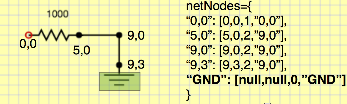
After doing unioning of GND with its pin, we get this.

Now remember how components returned a simplified description. Those are always done in terms of immediate names. They aren’t the final unioned set representative. For example we would get [“R”,[“0,0″,”5,0”],1000] rather than the canonical effective names [“R”,[“0,0″,”GND”],1000]. So before display them, we need to lookup the final name by traversing the parent tree (this is the findSet() algorithm for disjoint forests).
Once we’re done with all this business, we can print out components we are interested in with lumped and unioned node names as shown below:
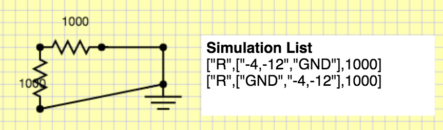
This representation is perfect, because we can use it to create a circuit simulation structure that actually can solve the circuit.
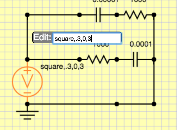
Editing component values
One last but important part is that we need some way to edit resistances, capacitances and set parameters for voltage sources. We could get arbitrarily complex, so for now, I am going to keep it simple. Every component just stores a string, and I can put whatever I want there. For the voltage source I am going to use <wavetype=sin|square|triangle>,<period in s>,<voltsMin>,<voltsMax>. Then, whenever somebody double clicks on a component, they will get an edit box to change the parameters. I might want to have more first class parameters types in the future, but this will get me by, and it took 5 minutes to implement! See here:
Moving on
That’s probably enough for this time. I have made considerable progress on the simulator, and I will discuss how that was constructed in the next segment. To wet your appetite on how that works, take a look at this video of the simulator in action…