Circuit Simulation Part IV: Nonlinear circuits and implementation

In the last part  we presented the major part of the UI, but we still hadn’t talked about the implementation of solving. In this post we will talk about how to actually solve non-linear equations both in theory and in implementation.

Non-linear circuits

Since last time, I took a pass at cleaning up the code and I decided to implement a few more components (inductors and diodes).   Inductors were relatively easy since it is still linear, but the diode presented more problems. Let’s go through the theory of non-linear solves.

We started in Part I laying out how to devise an equation per KCL node. Each equation becomes a row in the matrix and then we just solve a linear system to get the final values. That’s all good and fine, but it only works for linear components like resistors, inductors, capacitors and simple source terms like voltages and currents. For things like diodes and transistors which have crap loads of annoying non-linear exponential crap in them, we are kinda screwed. So, we must turn to nonlinear solving techniques, in particular Newton-Raphson iteration which root solves non linear equations by solving linear approximations and iterating. Let’s do a brief overview to see what we’ll need. Let’s suppose the ith equation
\mathbf{F}_i(\mathbf{x}) = 0
But since \mathbf{F} this is nonlinear. So using the taylor approximation we can write an approximation to the function as
 \mathbf{F}_i(\mathbf{x}) \approx \mathbf{F}_i(\mathbf{x}^{n}) + \left. \frac{\partial \mathbf{F}}{\partial \mathbf{x}} \right|_{\mathbf{x}^n}\delta\mathbf{x}
where \delta\mathbf{x} = \mathbf{x}^{n+1} - \mathbf{x}^n and \partial\mathbf{F}/\partial\mathbf{x}|_{\mathbf{x}^n} is the Jacobian at the current iterate.
We still want the root to the approximation so we need to now solve
\mathbf{F}_i(\mathbf{x}^{n}) + \left. \frac{\partial \mathbf{F}}{\partial \mathbf{x}} \right|_{\mathbf{x}^n}\delta\mathbf{x} = 0
or specifically
 \left. \frac{\partial \mathbf{F}}{\partial \mathbf{x}} \right|_{\mathbf{x}^n}\delta\mathbf{x} = -\mathbf{F}_i(\mathbf{x}^{n})
Colloquially this is just a matrix equation \mathbf{A x}=\mathbf{b}. However, every Newton iteration we need to form a new A matrix. Thus given a current solution state \mathbf{x}_i we can go to a new one by following the steps:

  1. Solve  \left( \left. \frac{\partial \mathbf{F}}{\partial \mathbf{x}}\right|\mathbf{x}^n \right) \mathbf{\delta x}= -\mathbf{F}( \mathbf{x}^n )
  2. Update the solution to be \mathbf{x}^{n+1} = \mathbf{x}^n + \mathbf{\delta x}

On each time step we just repeat 1 and 2 as many times as needed for convergence given some norm. I just use check if \mathbf{\delta x} is small for now. So to implement this, we need a way to form the matrix, a way to compute derivatives and a way to solve matrices.

Implementation

Building a matrix

Conceptually, we need to form a matrix every time step and every Newton step. This requires two steps, identifying all the unknowns (which defines matrix dimensions), followed by determining the coefficients of the matrices. For various reasons (that probably are invalid and I will have to fix later) I thought it would be good to use separate objects for the solve and the UI. Thus, in the last segment we had a function that took “Symbol” objects and produced a final description like:

["R",["n1","n2"],1000]
["C",["n2","GND"],0.0001]
["V",["n1","GND"],"square,0.1,-1,1"]

We will go through the list and make “solver” objects now. It looks like this:

function createCircuitFromNetList(names,components){
    circuit=new Circuit();
    // Make a list of all the voltage nodes to graph
    namesToGraph=[]
    for(var n in names) namesToGraph.push(n);
    // Take visual components and turn them into simulation components
    for(var n in components){
        var node=components[n];
        switch(node[0]){
            case "R": circuit.addR(node[1][0],node[1][1],node[2]);break;
            case "C": circuit.addC(node[1][0],node[1][1],node[2]);break;
            case "V": circuit.addVoltage(node[1][0],node[1][1],node[2]);break;
            case "D": circuit.addD(node[1][0],node[1][1],node[2]);break;
            case "L": circuit.addI(node[1][0],node[1][1],node[2]);break;
        }
    }
    // solve and graph the circuit
    var foo=circuit.transient(3.0,.005,namesToGraph);
    graph(0,2,namesToGraph,foo);
}

Now essentially, we have connected up our UI part to our solver part. From here on out we are going to talk about the parts of the solver. It is possible to use those parts without a UI in a sense, so we basically have some compartmentalization!

Let’s look at what addR and addVoltage do because they are interesting:

Circuit.prototype.addVoltage=function(name1,name2,value){
    n1=this.allocNode(name1)
    n12=this.allocNode("sc"+this.num)
    n2=this.allocNode(name2)
    this.components.push(new Voltage(n1,n12,n2,value))
}
Circuit.prototype.addR=function(name1,name2,R){
    var n1=this.allocNode(name1)
    var n2=this.allocNode(name2);
    this.components.push(new Resistor(n1,n2,R))
}

The allocNode assigns that named node a number in the unknown vector. Once that is done, we make the component object using only the numbers. Each object knows how to contribute to the matrix and which values it contributes to. So in the example above we’d probably assign the matrix unknowns as [n1,n2,GND,sc3]. And remember these unknowns are going to actually be the delta in those values rather than the values themselves. Let’s look at how Resistor is implemented:

function Resistor(node1,node2,R){
    this.node1=node1
    this.node2=node2
    this.oneOverR=1.0/R
}
Resistor.prototype.matrix=function(dt, time, system, vPrev, xOld){
    system.addToMatrix(this.node1,this.node1,this.oneOverR);
    system.addToMatrix(this.node1,this.node2,-this.oneOverR);
    system.addToMatrix(this.node2,this.node1,-this.oneOverR);
    system.addToMatrix(this.node2,this.node2,this.oneOverR);
    system.addToB(this.node1,-vPrev[this.node1]*this.oneOverR+vPrev[this.node2]*this.oneOverR);
    system.addToB(this.node2,+vPrev[this.node1]*this.oneOverR-vPrev[this.node2]*this.oneOverR);
}

The constructor caches the nodes and the conductance (inverse of resistance). The matrix function is where all the magic happens. The function is called from the global build matrix function for all components. Several arguments are provided which are important to be able to add to the matrix. dt is the time step, time is the current time we are simulating at (good for voltage sources), system is an interface for adding values to the matrix, vPrev is the last newton iteration value (x^{n-1} in notation above). Why am I using v instead of x? Because I was stupid when I started writing this and thought everything would be a voltage, but clearly that can’t work. system provides two functions to use addToMatrix() and addToB that add stuff to the A matrix and the b right-hand-side, respectively. Everything we do to the matrix is opposite and equal and thus we always end up with a symmetric matrix, which is to be expected from a physical system. Also note that it is the linearity of the derivative that lets us differentiate the contribution to the full nodal equations for just the one component we are considering here.

Let’s dig into the math of the derivatives for a second. The contribution to the current of a resistor to a node will be I=V/R based on ohm’s law. So suppose we have a resistor for n_1 to n_2. Then we have a contribution of n_2/R-n_1/R on n1’s net current and n1/R-n2/R net current. Differentiating with respect to each variable yields on each equation gives the Jacobian. These nodal equation derivatives only contribute to the rows corresponding to the KCL current and the only columns that are non-zero are the ones where the variable is n1 or n2. The derivative w.r.t. to either n1 or n2 gives 1/R (this is why we cached the conductance). Thus if this was the only equation our partial Jacobian matrix would look like
 \left(\begin{array}{ccccc} 0& \vdots & 0& \vdots & 0 \\ \cdots & 1/R & \cdots & -1/R & \cdots \\ 0& \vdots & 0& \vdots & 0\\ \cdots & -1/R & \cdots & 1/R & \vdots \\ 0 & \vdots & 0& \vdots & 0\\ \end{array} \right)
You can think of each component producing its own Jacobian matrix and just adding them all. Implementing the code like that would be very slow, so instead, we have this addToMatrix function do the same thing for us. On the right hand side we just evaluate the ohm’s law contributions with respect to the vPrev values. Thus our final system contribution from just the resistance in this particular case is
\left(\begin{array}{cccc} 1/R & -1/R & 0 & 0 \\ -1/R & 1/R & 0 & 0 \\ 0 & 0 & 0 & 0 \\ 0 & 0 & 0 & 0 \\ \end{array}\right)\left(\begin{array}{c} n_1 \\ n_2 \\ \textrm{GND} \\ \textrm{sc3} \\ \end{array}\right) = \left( \begin{array}{c} -\textrm{vPre}_0/R+\textrm{vPre}_1/R \\ \textrm{vPre}_0/R-\textrm{vPre}_1/R \\ 0 \\ 0 \\ \end{array}\right) .
This is consistent with the code presented above.

Now that we’ve built the matrix for the resistor, let’s build it for the voltage source. The voltage has three matrix equations it contributes to. The two current equations for the nodes it is connected to and its own current which is unknown. From our example we have that n_1-n_2=v(t) where v is the voltage source that only depends on time. But we also have the unknown sc3 which contributes to the KCL current equation for n1 and GND. Thus this function

Voltage.prototype.matrix=function(dt,time,system,vprev,vold){
    // the constraint that the voltage from node1 to node2 is 5
    var v=5; // default to DC of constant 5 v
    if(this.type=="sin"){ 
    	v=(Math.sin(time*2*Math.PI/this.period)+1)*(this.max-this.min)*.5+this.min
    }
    // constrain the voltage
    system.addToMatrix(this.nodeCurrent,this.node1,1);
    system.addToMatrix(this.nodeCurrent,this.node2,-1);
    system.addToB(this.nodeCurrent,v-(vprev[this.node1]-vprev[this.node2]));
    // nodeCurrent is the current through the voltage source. it needs to be added to the KVL of node 1 and node2
    system.addToMatrix(this.node1,this.nodeCurrent,-1);
    system.addToMatrix(this.node2,this.nodeCurrent,1);
    system.addToB(this.node1,vprev[this.nodeCurrent]);
    system.addToB(this.node2,-vprev[this.nodeCurrent]);
}

yields on our example the matrix
\left(\begin{array}{cccc} 0 & 0 & 0 & -1 \\ 0 & 0 & 0 & 0 \\ 0 & 0 & 0 & 0 \\ 1 & -1 & 0 & 0 \\ \end{array}\right)\left(\begin{array}{c} n_1 \\ n_2 \\ \textrm{GND} \\ \textrm{sc3} \\ \end{array}\right) = \left( \begin{array}{c} 0 \\ 0\\ 0 \\ v(t) \\ \end{array}\right) .
It is somewhat weird that GND has all zeroes after my lecture about equal and opposite and symmetry. Well, the upshot is that GND is set to be zero, so we don’t let the matrix or right hand side get any contributions there (it is in the implementation of addToMatrix and addToB). At the end of the matrix construction we set the on-diagonal element for the gnd node row to be 1 which means that we enforce the equation gnd=0.

Each component has a similar implementation. Some are more complicated and need vOld as well (capacitors need to computer voltage derivatives). Since everybody has a definition, we have a simple buildMatrix function that makes the whole matrix:

Circuit.prototype.buildMatrix=function(vPrev,vOld,dt,time){
    var system=new System(this.num,this.ground);
    this.sys=system;
    for(var comp=0;comp<this.components.length;comp++){
        this.components[comp].matrix(dt,time,system,vPrev,vOld);
    }
}

Solving a matrix

Now we have constructed the matrix in our System object (which you need to look at the source code for). It basically consists of a array of arrays member called A and a array member consisting of b. We can solve the matrix equation using Gaussian elimination which we have just implemented in a straightforward way using partial pivoting (column swapping). Nothing exciting here, you can go look at wikipedia for more information on Gaussian elimination. That being said, using a dense matrix and gaussian elimination may not be the most efficient solver here. At least using a sparse LU or other optimized direct solver would be better. You could use LAPACK or SparseLU or whatever if you were in C/C++/Fortran. I am just in it for a quick and fast demo, but many opportunities for improvement are available which would be essential to make large circuits (1000’s of components) really efficient.

The Newton Solve

The full loop is implemented in transient() and it basically follows these steps:

function transient(maxTime,dt){
    vOld=vector(N,0); // N entries that are all zero
    vPrev=vector(N,0); // N entries that are all zero
    while(time<maxTime){
        vPrev.copyVector(vOld);
        for(var newton=0;newton<maxNewtonSteps;newton++){
            var matrix=buildMatrix(vPrev,vOld,dt,time);
            var difference=solve(matrix); /
            var maxDiff=difference.maxNorm();
            vPrev.addVector(difference)
            if(maxDiff < diffTolerance) break; // converged!
        }
        vOld=vPrev; // copy values
        time+=dt;
    }
    return vOld;
}

This is basically everything that is needed. There are several things that can go wrong. If you don’t specify a gnd, the solve will not work. If you make a loop of capacitors it probably won’t work. If you don’t have everything connected in a consistent way, it won’t work. There is very little error checking right now. It would be good to check if ground is connected. It would be good to check if the matrix is non-singular on every newton step.

A Diode

Before we finish let’s go through how the diode is implemented. This is a very important part because it is usually not talked about in simple circuit solvers that only do linear elements. A diode can be modeled by the Shockley equation that relates current to voltage
 I=I_S \left( e^{\frac{V_D}{n V_T}} - 1\right)
where I_S is the saturation current of the diode, V_T is the thermal voltage (26 mV at room temperature according to wikipedia) and n varies between 1 and 2 to represent how ideal the diode is. Suppose we have nodal voltages n1 and n2, then we have  I_S \left( e^{\frac{n_1-n_2}{n V_T}} - 1\right). The derivatives with respect to n1 and n2 are
 \pm \frac{I_S}{n V_T} e^{\frac{n_1-n_2}{n V_T}}, respectively.

All this fun can be encoded into a component function that looks like this:

Diode.prototype.matrix=function(dt, time, system, vPrev, vOld){
	var n1=this.node1;
	var n2=this.node2;
	var denomInv=1./this.n*this.VT;
	var value=this.IS*(Math.exp((vPrev[n1]-vPrev[n2])*denomInv)-1)
	var deriv=this.IS*(Math.exp((vPrev[n1]-vPrev[n2])*denomInv))*denomInv;
	system.addToMatrix(this.node1,this.node1,deriv);
	system.addToMatrix(this.node1,this.node2,-deriv);
	system.addToMatrix(this.node2,this.node1,-deriv);
	system.addToMatrix(this.node2,this.node2,deriv);
	system.addToB(this.node1,-value);
	system.addToB(this.node2,value);
}

Using this we can now make a bridge rectifier circuit plus filter to turn AC into DC currents with minimal ripple.
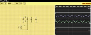
bridgeRectFix

Graphing

The transient() function populates arrays for each value it is requested to collect. These are then send to the graph() routine which is basically a html5 canvas draw routine that puts those on the graphs on the right. See the code for more details, nothing super exciting there. I would like to make the graphing selective and have the ability to graph some quantities on the same graph window, but this suffices for now. I would also like to extend the simulator to produce currents for every element as well. That will likely require some rework to how the matrices are created which will make the union find from the last post less important.

Try it yourself

You can now try the program online at http://www.andyselle.com/circuit/.
There is still a lot more to do to make this an awesome circuit simulator, but it’s basically working. Yay! Here’s another example I did with some weird non-linear inductor behavior
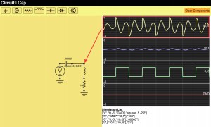
inductors


Circuit Simulation in Javascript Part III: Making the UI useful

Finally, I am picking up my long delayed circuit simulator. It’s been almost a year, so it is long overdue. There is no better time to do pointless educational programming projects than while vacationing. If you want to have a quick view of where we have gotten, see the youtube video at the bottom!

Anyways, in the part I we laid out the math for basic linear passives. In part II we made some of the UI for schematic capture. In this part we will advance the UI considerably. Below is a description of more problems we had to solve.

Adding components and adding wires

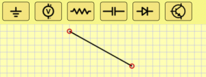
We now allow adding wires by clicking and dragging and we have a palette of components that can be added on demand. This was fairly uneventful. We also added “Backspace” and “r” as key options to delete and rotate the highlighted component.

palette

Managing connections

Allowing users to connect components is probably the trickiest part of the UI. The basic idea I came up with is to always assume we are on a grid. Every pin will always lay on exactly aligned to the grid. If two components pins are on top of each other then they are considered connected. Let’s get into the implementation.

To do this, we need a data structure that can map from a location to which component(s) (or at least how many) are incident at the location. A major design constraint is that we want it to be sparse, that is we don’t want a dense array of the grid nodes, so we actually implement this as a hash table. For simplicity we just consider the key of the hash table to be the string xCoord+”,”+yCoord (so it is human readable). Probably it would be more efficient to do some bit fiddly stuff like ((x&0xffff)<<16)+(y &0xffff), but we are just making something simple, so I’m going to punt on that aspect of performance.

Each UI operation will call functions on every editable component called buildNet(recordNet,unionNet). recordNet and unionNet are functions that the component can call to record any pin’s grid coordinates and unionNet let’s the component consider two grid coordinates to be connected (i.e. a wire uses these). For a resistor the buildNet() function looks like this:

ResistorSymbol.prototype.buildNet=function(recordNet,unionNet)
{
   var n1=recordNet(this.objectToWorld(0,0));
   var n2=recordNet(this.objectToWorld(10,0));
   return ["R",[n1,n2],this.value];
}

This registers the two pins of the resistor and returns a full description of the resistor for the net list (more on that later). The WireSymbol not only registers new nodes but also unions the two nodes into one conceptual node:

WireSymbol.prototype.buildNet=function(netRecord,unionNet){
   var n0 = netRecord(
             this.objectToWorld(this.points[0][0],this.points[0][1]));
   var n1 = netRecord(
             this.objectToWorld(this.points[1][0],this.points[1][1]));
   unionNet(n0,n1);
}

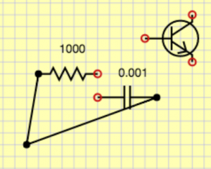
What does netRecord do? Basically it makes grid location based name and puts it into a hash table with the key being the name and the value being [<xcoord>,<ycoord>,<numberOfComponentPinsIncident>,<parentSet>]. xcoord and ycoord are obvious, <numbertOfComponentPinsIncident> allows us to draw an open circle when there is 1 unconnected pin, and a solid circle when everything is connected. Each component pin that touches this grid node increments that value. Lastly, parentSet is the name of the parent set in which we are contained. This will be explained below in the union set finding. The result of the buildNet() function is we have a data structure the UI can query when it is drawing to make open or closed circles at the pin locations.

connections

Creating the net list

Given a schematic, we would like to create a net list which is a description of what the components are and how they are connected. This is different than the schematic which has extraneous spatial information. For simulation we want a distilled description with only bare essentials needed for the simulator. In basic circuit analysis we use the lumped element model where any wire connections are assumed to be ideal. That means that any pins connected by wires become a single node. To accomplish this, we need to track connected components, so we will use a disjoint forest tree algorithm. For simplicity I am going to omit using the rank heuristic, but that would be easy to add to get the coveted inverse Ackermann function big-O performance. Remember the <parentSet> item in the node hash table discussed above. We start that equal to the key in the hash table. This means that the node is its own parent. Since everybody starts that way, everybody starts as a set of 1. Any unioning will change one of the parent entries to be the other. This implies trees and we can always find the effective name of the set by following parent links from a given node. To see this in action, consider this circuit where no unioning has been done:

step1

If we union one of the wire’s two pins we get:step2

If we union the other wire we get:step3

This is all good and find, but we actually need to handle GND specially.Anything that unions with GND gets parent being GND. GND basically has ultimate priority over everybody. To do this, we have a special GND entry.step4

After doing unioning of GND with its pin, we get this.
step5real

Now remember how components returned a simplified description. Those are always done in terms of immediate names. They aren’t the final unioned set representative. For example we would get [“R”,[“0,0″,”5,0”],1000] rather than the canonical effective names [“R”,[“0,0″,”GND”],1000]. So before display them, we need to lookup the final name by traversing the parent tree (this is the findSet() algorithm for disjoint forests).

Once we’re done with all this business, we can print out components we are interested in with lumped and unioned node names as shown below:

exampleUnioned

This representation is perfect, because we can use it to create a circuit simulation structure that actually can solve the circuit.

Editing component values

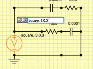
One last but important part is that we need some way to edit resistances, capacitances and set parameters for voltage sources. We could get arbitrarily complex, so for now, I am going to keep it simple. Every component just stores a string, and I can put whatever I want there. For the voltage source I am going to use <wavetype=sin|square|triangle>,<period in s>,<voltsMin>,<voltsMax>. Then, whenever somebody double clicks on a component, they will get an edit box to change the parameters. I might want to have more first class parameters types in the future, but this will get me by, and it took 5 minutes to implement! See here:

editor

Moving on

That’s probably enough for this time. I have made considerable progress on the simulator, and I will discuss how that was constructed in the next segment. To wet your appetite on how that works, take a look at this video of the simulator in action…

Circuit Simulation Part II – Schematic Capture using HTML5 Canvas

Ok, we need to be able to create circuits in the web interface. The basic idea will be how to use a HTML5 canvas to draw the schematic and use mouse events to manipulate the schematic. The first order of business is to have a Component class. This will know where the component is located at, generically know how to draw stuff and also know how to do movement, selection etc. We’ll start with a simple interface. Before we do that we need a class to contain everything about the schematic. We’ll do this with SchematicCapture. This will know about the list of components and it will also know things about how the view is defined.

I’ll warn you ahead of time, my HTML5 experience and prowess is not very strong. I am much more comfortable and accomplished in C++, and I’m sure I’m doing some horrible things that are horribly inefficient and brain damaged. This whole project is really just an educational experiment to see how good a UI made entirely in JavaScript is and how I can create one.

I’ll remark that I did discover a similar project to this one that is part of the MIT open courseware circuit course tool. Undoubtedly they did a better job than I did, but I’m trying to do this on-my-own in true not-invented-here fashion. I am also trying to document how I solve the problem step by step, mistakes and all.

Basic drawing

We’re going to use the notion of a windowing transform. Basically we have device coordinates which are the pixel locations, but we want a virtual canvas so we’re going to have “world” coordinates. The way we transform back and forth is quite simple. First, we have the notion of a xmin, xmax, ymin, ymax window we would like to view and we know our device is from canvas.width by canvas.height. To convert from device to world we make two functions to convert from world to device coordinates as

var xToDevice=function(x){return (x-xmin)/(xmax-xmin)*width};
var yToDevice=function(y){return (y-ymin)/(ymax-ymin)*height};

The first thing we need is a grid. We will make a grid line every dx. To draw the x grid we have the following code. First, we draw the background in yellow and then we draw the x lines in blue. We use floor to figure out where to start drawing the line to define xstart and then we continue until we go past xmax. Even though clipping would allow us to draw beyond, it would inefficient (and infinitely so) to draw everyline everywhere.

SchematicCapture.draw = function(){
    ...
    // draw grid lines
    context.fillStyle = "rgba(255, 255, 180, 255)";
    context.fillRect(0, 0, width, height);
    var dx=1;
    context.strokeStyle = "rgba(100, 100, 255, .5)";
    var xstart = Math.floor(xmin / dx);
    for(var x=xstart;x<xmax;x+=dx){
        context.moveTo(xToDevice(x),yToDevice(ymin));
        context.lineTo(xToDevice(x),yToDevice(ymax));
    }
    ...	

Now we get something that looks like this… I know super exciting…

grid

Once we have that abstraction we can delegate drawing to each component in our list as:

// draw symbols
SchematicCapture.draw = function(){
    ... 
    for(var v in this.symbols){
        this.symbols[v].draw(xToDevice,yToDevice,context);
    }
    ...
}

This is exciting, now we are ready to define a generic component. The main idea is we will have a list of points that the component knows to draw and a generic point that loops through and draws the points. The basic component will store a location and a rotation (0,1,2,3) for no rotation, 90 degrees, 180 degrees and 270 degrees. To do this we need three basic functions on our component: the constructor, the objectToWorld to transform points from object space to world space, and the draw which will draw the component.  Here are the basic three functions for the component

// Construct a component at a given position and rotation
Component = function(x,y,rotation){
    this.x = x; // xlocation of origin in world space
    this.y = y; // ylocation of origin in world space
    this.rotation = rotation; // 0 to 2
    // compute the bounding box
    this.box = [1e7,-1e7,1e7,-1e7];
    for(var ptK in this.points){
        var pt = this.points[ptK];
        if(!pt) continue;
        var pt = this.objectToWorld(pt[0],pt[1]);
        this.box[0]=Math.min(this.box[0],pt[0]);
        this.box[1]=Math.max(this.box[1],pt[0]);
        this.box[2]=Math.min(this.box[2],pt[1]);
        this.box[3]=Math.max(this.box[3],pt[1]);
    }
}

// Transform from object space to world space a point x,y
Component.prototype.objectToWorld=function(x,y){
    if(this.rotation==0) return [x+this.x,y+this.y];
    else if(this.rotation==1) return [this.x+y,this.y-x];
    else if(this.rotation==2) return [this.x-x,this.y-y];
    else if(this.rotation==3) return [this.x-y,this.y+x];
}

// Draw a component at a given location
Component.prototype.draw=function(xToDevice,yToDevice,context){
    context.beginPath();
    //var points=[[0,-1],[0,0],[2,0],[2.5,-1],[3.5,1],[4.5,-1],[5.5,1],[6.5,-1],[7.5,1],[8,0],[10,0]]
    var first=true; // first point has to be a moveTo
    for(var dummy in this.points){
        var ptOrig=this.points[dummy];
        // check if we are at a null point and reset the draw count
        if(ptOrig == null){first = true;continue;}
        // transform the point into world device coordinates
        var pt=this.objectToWorld(ptOrig[0],ptOrig[1]);
        if(first){
            context.moveTo(xToDevice(pt[0]),yToDevice(pt[1]));
            first=false;
        }else{
            context.lineTo(xToDevice(pt[0]),yToDevice(pt[1]));
        }
    }
    context.stroke();
    // draw a label for the value of the component
    var pt=this.objectToWorld(3.5,-3.5);
    context.font = "10pt sans-serif"
    context.fillStyle = "#000000";
    context.fillText(this.value,xToDevice(pt[0]),yToDevice(pt[1]));
}

Now, we just need to define subclasses to define our component types. For example, here is our resistor component definition

ResistorSymbol =  function(x,y,rotation){
    this.points=[[0,-1],[0,0],[2,0],[2.5,-1],[3.5,1],[4.5,-1],[5.5,1],[6.5,-1],[7.5,1],[8,0],[10,0]]
    Component.call(this,x,y,rotation)
    this.value = "1k"
}
ResistorSymbol.prototype = new Component()

We can create definitions for capacitors, voltage sources and everything else we need similarly. If we hard code a few component constructors in our SchematicCapture class instantiation, we get something that looks like this:

components

Not bad!

Basic selection and interaction

Schematic capture is really not very good for anything unless we can move things around and add components. Let’s attack the problem of moving things around. Basically the idea is that we’ll register mouseDown, mouseUp and mouseMove handlers, and in the mouseDown we’ll find if we have selected anything to control how the other handlers work. We’ll use the bounding boxes that we have created as a simple way of knowing whether the given world-space coordinates are inside a component. We’ll just use linear search for now, but one could imagine making a bounding box hierarchy or something smarter to get down to some sub-linear (maybe logarithmic) time.

Highlighting

First thing I implemented was highlighting. This will make sure I have the coordinates transforming properly and the bounding boxes
bounding properly. I needed to do some refactoring, but the main thrust consists of delegating mouseMove to the schematic (which involved storing a pointer to the schematic type from the canvas type). The mouseMove implementation also needs to be augmented to check if we are inside something and if we are make it redraw in a nice color. Here’s mouseMove.

SchematicCapture.prototype.mouseMove =  function(event){
...
        var oldHighlight = this.highlight;
        this.highlight=null;
        for(var v in this.symbols){
            var symbol=this.symbols[v];
            if(symbol.inside(newX,newY)){
                this.highlight=symbol;
            }
        }
        if(this.highlight != oldHighlight) this.draw(); // only draw if we changed highlight
}

Here we have used the inside function on the component to check if a given world coordinate is inside a given world bounding box. Its implementation is this:

Component.prototype.inside=function(xWorld,yWorld){
    return xWorld > this.box[0] && xWorld < this.box[1] && yWorld > this.box[2] && yWorld < this.box[3];
}

In addition to actually affect how drawing happens, we made SchematicCapture.draw() send the highlight flag into the Component.draw. I’ll spare you the annoying details.

Basic movement

Now that we have highlighting working we need to attack the more difficult task of movement. I’m going to just assume we need one selection for now to move. I’d like to have multi-select with shfit and marquee (a.k.a. bounding box) select working but all that jazz is complicated and I want to start simple.

Implementing these mouse interaction routines I’ve done about a billion times now, starting with OpenGL in my intro graphics class using fltk. In javascript it works pretty much the same as fltk, win32, gtk, Qt, and every other graphics library I have ever used. The best way to do these things is to remember the coordinate of the event that you last handled in the schematic class. Then when you get a new mousemove or whatever event you can look at the difference and add that as an offset to the component position you are currently selecting. In pseudocode

mouseDown(){
    this.x,this.y=event.x,event.y
    this.dragging=highlightedObject;
}
mouseMove(){
    offx,offy=event.x-this.x,event.y-this.y
    if(this.dragging){
        this.x,this.y=event.x,event.y
        highlightedObject.addOffset(offx,offy)
    }
}
mouseUp(){
    this.dragging=false;
}

Ok, it turned out to be a little bit more complicated than that. For one thing, I actually store the event x and event y in world space so I don’t need to double transform. Another major thing I wanted for the schematic capture was to clamp to a grid. To do this we might have fractional mouse movements with respect to the snapping grid. To avoid trouble with this and ensure simplicity, during interaction I keep an extra position for each moved component. This is done by the addOffset() function. It basically stores the x,y in this.fracX and this.fracY on the object, but it also rounds to create the this.x and this.y. This makes the rounding hysteresis work properly. In mouseUp I call a routine to drop the fraction in fracX , fracY and synchronize it to be the same as x,y. addOffset() is nice to break into its own function because I can do the handling of fractional positioning while at the same time being sure to update the world bounding box.

Adding wires

Adding wires is an important thing in that we need to be able to connect different components. Connections seem like they are going to be harder. Lets start out less ambitious and just represent line segments. I think that if we can have line segments just be a component like we already had, that will work nicely. Unlike other components, rotation probably doesn’t make sense, but lets just leave that in and ignore that for now. The basic method of representing a wire will be to use the position of the first end point of the wire and then store an offset to the second wire. So we’ll have two points in our base class draw [[0,0],[dx,dy]] where dx,dy = x2-x1,y2-y1.

One challenge is that we need to implement an inside function that will allow us to query whether we are close to the line segment. That turns out to be a simple linear algebra problem which is described in this diagram. Basically we make two vectors between the first point of the wire and the query point of the moues cursor and the second point in wire and compute cross product and dot product. That gives us values that can be used to measure perpendicular and parallel distance. You could also think about it as rotating the coordinates of the cursor position and translating them into a reference frame  where the wire AB is along the x-axis. That begs the question why not just represent the wire with that as the object space, and that might make the inside test easier, but it really is just pushing the problem around and it would force us to support non-axis aligned rotations for components. So we’ll just do this in the inside call

wireInside


The code corresponding to the wire component is:

WireSymbol = function(x,y,x1,y1){
    this.points=[[0,0],[x1-x,y1-y]];
    Component.call(this,x,y,0)
}
WireSymbol.prototype = new Component()
WireSymbol.prototype.inside=function(xWorld,yWorld){
    // v1 is vector from first point of wire to the cursor position
    // v2 is the vector from the first point to the second wire normalized
    // dotProduct(v1,v2) = cos(theta) |v1| |v2| = cos(theta) |v1|  must be in the interval [-threshold,v1+threhsold]
    // crossProduct(v1,v2) = sin(theta) |v1| |v2| = sin(theta) |v1| must be within [-threhsold,|v1|+threshold]
    var wireInsideThreshold = 0.5
    var len=Math.sqrt(this.points[1][0]*this.points[1][0]+this.points[1][1]*this.points[1][1]);
    var invLen=1./len;
    var v1=[xWorld-this.x,yWorld-this.y];
    var v2=[this.points[1][0]*invLen,this.points[1][1]*invLen];
    var parallelDistance=Math.abs(v1[0]*v2[1]-v1[1]*v2[0]); // length of perpendicular segment i.e. distance from light containing segment
    var perpendicularDistance=(v1[0]*v2[0]+v1[1]*v2[1]); // projected point parameter
    return Math.abs(parallelDistance) < wireInsideThreshold && perpendicularDistance > -wireInsideThreshold && perpendicularDistance < len+wireInsideThreshold
}

Remaining things to do

I think that is enough for today. Let’s reflect and see where we are. We got a couple of things done.

  • Basic drawing of gridlines and canvas
  • Basic component infrastructure with wires, voltage sources, resistors, and capacitors visualized

We still have a ton to do that we should leave for a future post

  • Interface to add components. Hopefully something like the “tab” convention in node-based graphics tools like Nuke and Houdini. Unobtrusive and fast!
  • Interface to add wires
  • Manage connections between components (need to track pins, wires overlapping pins and other wires)
  • Deletion of components
  • Selection/manipulation of multiple components
  • Zooming and scrolling of virtual schematic
  • The actual simulator!

There are several could be betters (CBBs) that we still have brewing:

  • The code is a mess. Better compartmentalization, naming, commenting would be good
  • We make too many temporaries (arrays). It’s hard to avoid without having functions for each component. I.e. look at transform(), we return an array.
  • We could probably increase abstraction and elegance by having a vector class. In C++ this is really cheap and is the way to go. In JavaScript this blows up the number of temporaries to high hell. In general I find JavaScript makes having abstract and elegant code that is performant much harder than C++. The sub-typing feels expensive compared to C++’s facilities like structs, templatization, inlining, and all that static goodness.

To see what we have go to the page or check it out embedded here (live)

Circuit simulation in Javascript Part I

As I’ve been trying to learn more about electronics, circuit simulation is an interesting route to go. No messy wires, can easily see idealized properties on a virtual oscilloscope, don’t have to wait for parts. Obviously there are limitations to models and nothing beats getting the real thing to work.

There are many SPICE derivatives that one can select. Perhaps the easiest to use is LTspice. The main innovation in the original spice paper was a practical bipolar transistor model that was suitable for simulation. The basic technique of SPICE varies based on what type of simulation. Currently I am interested in the transient analysis which gives a time varying definition of the voltage and current for any point in the circuit. There are other modes and even the simplest operating point analysis (tutorial on the eevblog) is powerful.

The project

SPICE is nice and all, but since I want to learn how things work, I thought I’d write a circuit simulator from scratch in JavaScript. It shouldn’t be that hard, and it should really hone my intuition about how circuits work in a way that is much funner than solving basic circuits. Ideally I’ll do this in phases. For the first version described here I’ll support

  • Ideal voltage sources
  • Manual hard-coded circuits in the javascript file
  • Resistors and capacitors (linear passives)
  • Oscilloscope like view

In a later version these features would be nice to have

  • Inductors and diodes (non-linear passives)
  • Ideal opamps
  • Transistors and FETs
  • Transformers

Theory on solving circuits

The basic method we are going to use is Kirchoff’s Current Law that states that the net incoming and outgoing current is zero. So, basically for any component that has k nodes, it will contribute to k KCL equations in the circuit. Basically we need to solve all of the KCL simultaneously, so this should basically imply we are solving a big matrix. So let’s do a simple circuit example:

circuit

Notice how I have specified a GND to the circuit. This is essential, if you don’t do this you can’t solve for voltages because they won’t be relative to any zero. Now that we have our circuit, we need to write the KCL laws for all the nodes which will form some of the constraints of our circuit solution.

Let’s denote voltage at A, B, GND to be v(A), v(B), v(GND), respectively. The KCL at B is clearly \frac{v(A)-v(B)}{100} - \frac{v(B)-v(GND)}{100} = 0. Note I have used Ohm’s law for R1 and R2 separately and each component incident on B contributed to the KCL for B.

Now the slightly tricky part, writing the KCL laws for GND and A, because we don’t directly know the current going through V1. There is no Ohm’s law to help us here. Probably I should have started this endeavear with current sources, but let’s just go with it. The major observation is that we need to introduce an unknown variable for the current through V1, we’ll call it i(V1). That gives us i(V1) - \frac{v(A)-v(B)}{100} = 0. Notice how this equation’s second term is the negative of the first term of the KCL at B. That is because these circuit elements contribute symmetrically to the linear system and so we will get a symmetric matrix if we do things right. This is a great property to have because there are special matrix solvers that are much more efficient but only apply to positive definite and symmetric matrices (i.e. conjugate gradient).

Next we should write KCL for the GND node. However, that really wouldn’t be particularly interesting, because we already know what v(GND) will be — zero. So we will use v(\textrm{GND})=0.

So now we have three equations but four unknowns v(A),v(B),v(G),i(V1). We need one more equation to have a fully determined linear system,. One fact we haven’t included is that the voltage between A and G should be 5. So that gives us v(A)-v(G)-5=0. If we write these all as a system we get

\begin{matrix}  \frac{v(A)-v(B)}{100} - \frac{v(B)-v(G)}{100} & = & 0 \\ v(G) & = & 0 \\ i(V1) - \frac{v(A)-v(B)}{100} & = & 0 \\ v(A)-v(G) - 5 & = & 0  \end{matrix}

We can rewrite this in matrix form (Ax=b) and we get

matrixUnordered

The rows can be reordered to reflect the symmetry better.

matrixOrdered

If we plug this into our favorite linear solver (in this case I’m using SAGE)

from numpy import arange, eye, linalg
a=1/100;
A=matrix([[-a,a,0,1],[a,-2*a,a,0],[0,0,1,0],[1,0,-1,0]]);
b=matrix([[0],[0],[0],[5]]);
linalg.solve(A,b)

array([[ 5.   ],
       [ 2.5  ],
       [ 0.   ],
       [ 0.025]])

In other words v(A)=5 volts, v(B)=2.5 volts (go voltage divider), v(G)=0 volts, i(V1)=0.025 A. Everything is as we expected. In the next part we see how to code this into something that doesn’t require all this manual effort.