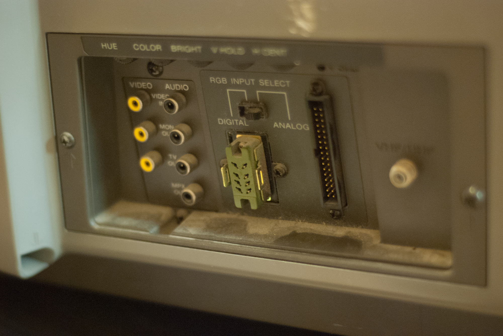
“The real winner seems to the be the great Sony KV-1311-CR monitor receiver. The praise lavished on this machine by the helpline callers was enough for me to actually go out and buy one for review and test.”
The big problem with using this monitor was getting it back to California intact. Moving CRTs requires lots of careful packaging. I used foam to pad the display, lots of bubble wrap before putting it into the box. Then I put that box in another box that was filled snugly with rolled up newspaper pages. Interestingly, the cheapest shipping option turned out to be checking it in my luggage (it cost only $35 (the price of an extra bag). Amazingly, it made it intact and working, though it looks like it was opened and searched (must be an uncommon item)/
The other big thing that I was concerned about was the pin numbering on the connector. I was concerned about how the pins were numbered on the ribbon connector. After scratching my head, the simplest way to figure it out was to find where the ground pins were (which I guess experienced people would say, duh, but hey I’m just a CS guy). So I just put my multimeter’s ground terminal onto the composite jack’s ground and found them. It turned out all the grounds were on one row (not the whole row, but almost). I can’t stress enough how frustrating this part was (doesn’t help to do this late at night). In fact, the numbering of the pins goes through one whole row and then to the other. This is different than an IDE which numbers swapping rows every pin number. I wanted to be absolutely sure, because I didn’t want to destroy a rare antique monitor by being careless.
The build
I have made cables many many times before. In fact, the first cable I made was an serial modem cable from Apple IIc DIN connector to IBM PC 9-pin connector to backup disks with ADT back in the 90’s. That cable was simply horrible (I didn’t even solder the wires because I didn’t have an iron or know how to solder). However, it did work. For this I wanted to do something a little more elegant. I figured I would create a PCB that had a male ribbon cable connector and the 15 pin male connector for the Apple IIgs side. Then, I can use a ribbon cable to connect to the monitor. If I get really clever, I could make a custom 3D printed cable housing for this. Doing a PCB for this does seem a little overkill, but it is not that crazy, considering OSHpark can produce boards dirt cheap, and I would need to find parts to make the hacked cable from anyways, why not do it right?
I’ve been using KiCad instead of eagle lately. Its routing is simply awesome compared to Eagle, but getting it setup is a real pain. Even so, I am very happy with it. Here is the basic schematic for the pinout. I really like making a schematic like this, because now I have documentation of how the cable works that I can share and refer to if anything goes wrong.
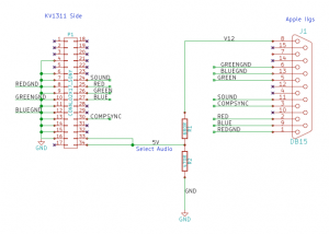 I quadruple checked all the connections. A neat factoid here is that both the Apple RGB connector and the sony have a pin for audio, so I decided to include that. Pin 33 enabled analog RGB (rather than IBM CGA style TTL RGB). Pin 34 enables audio. The resistors in the divider here are not important, and in my implementation I used a 3k3 and 2k instead of 680 and 470. You just need to generate 5 volts. Ideally I would twist the signal specific GND’s, but I didn’t do that and it worked fine (see below).
The Build
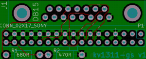
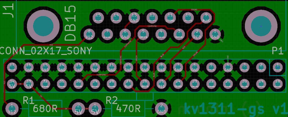
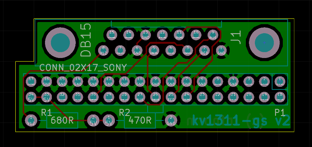
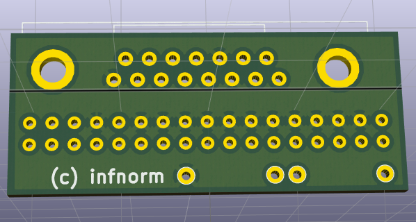
Once I had designed the schematic I checked everything again, and I made footprints for the schematic symbols (I think how KiCad does this makes a lot of sense rather than the eagle method). This is where I made a mistake :(, but we’ll get to that in a second. Here is the completed route which was quite easy to do with the push and shove routing!
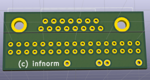
and here is the for-free 3D model that KiCad produces. One day I need to learn how to model things in Wings3D so I can see populated board previews.
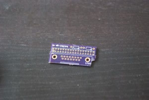
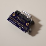
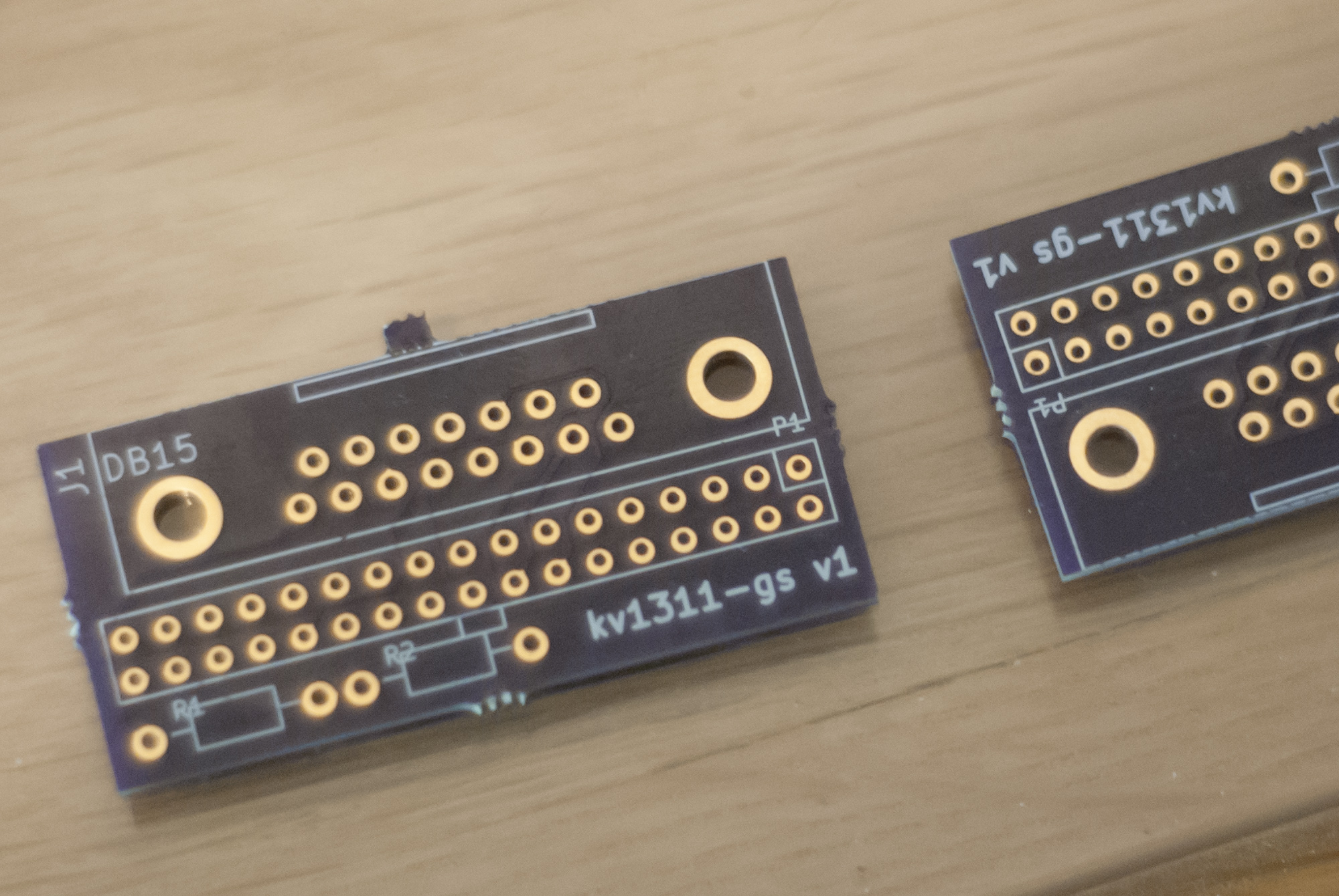
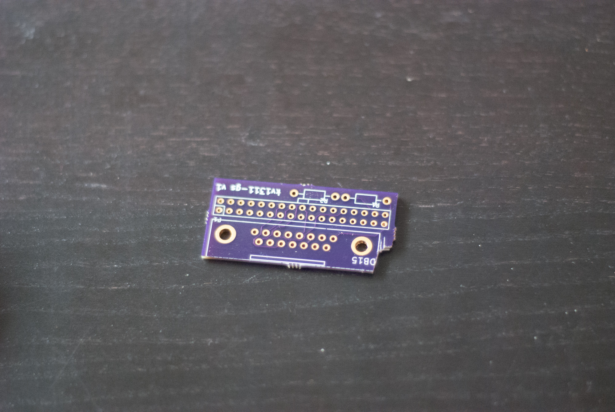
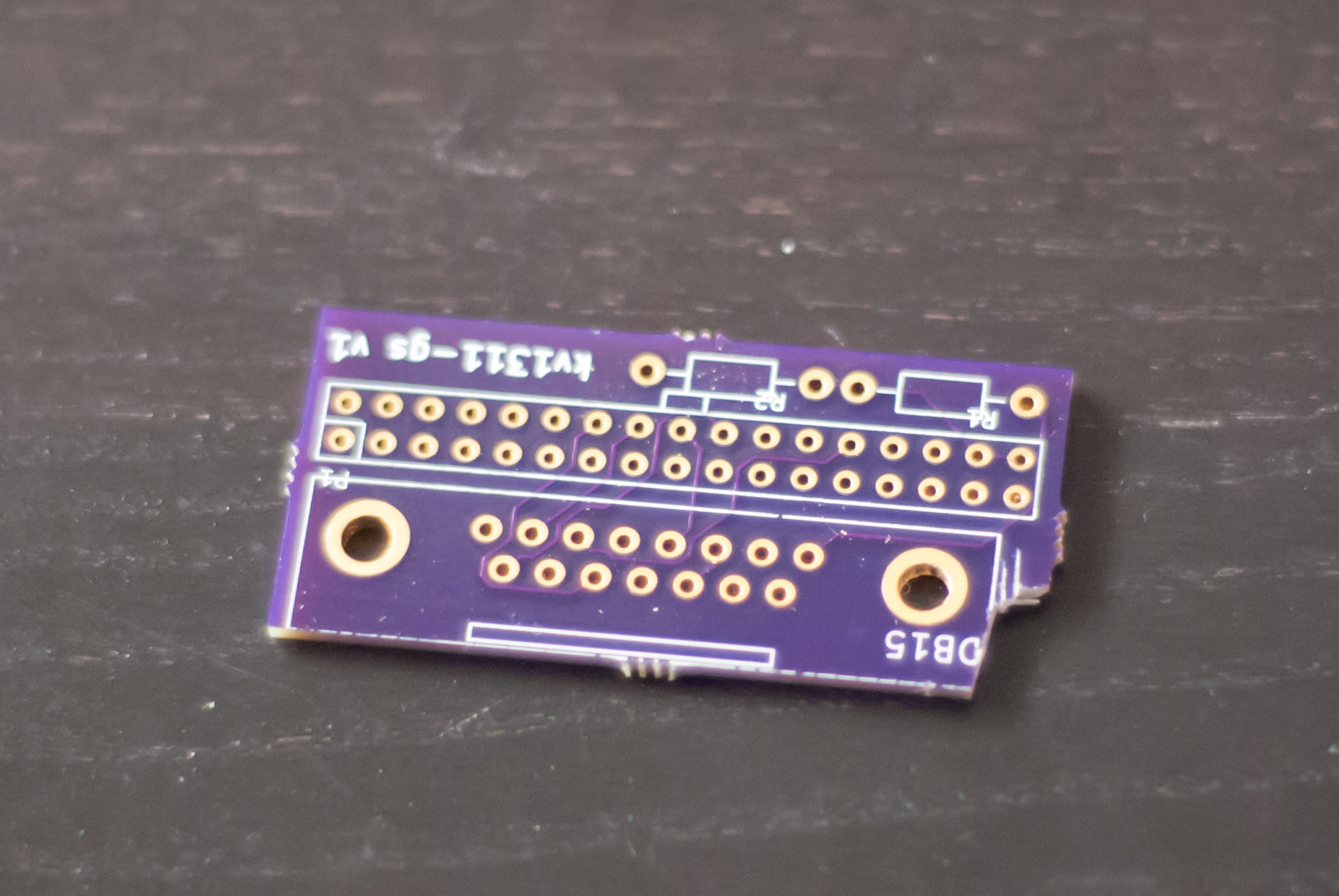
 Now it was time to produce the board. This only requires one side, so I could easily etch it myself, but I have to get a drill press, and my VGA board was ruined twice by my inability to drill accurate holes. Doing dozens of pins that have to be exactly straight and aligned is really hard. Also, this board is really small, so it would only cost $5 to make with OSHpark. Furthermore, I was going on vacation to Utah for two weeks, so I was not in a hurry. So I sent it off before I went on vacation. When I got back, it had arrived and it looked like this
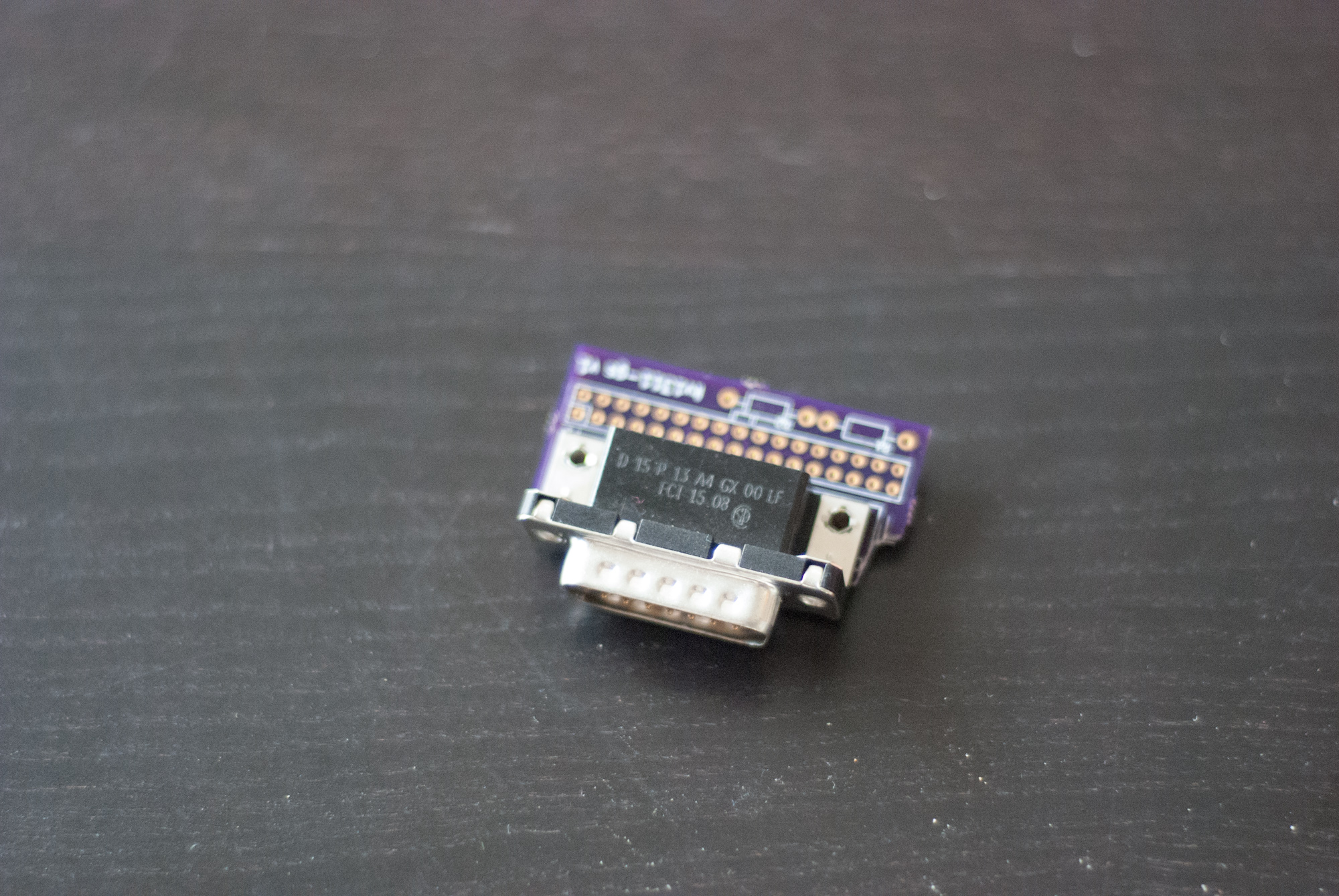
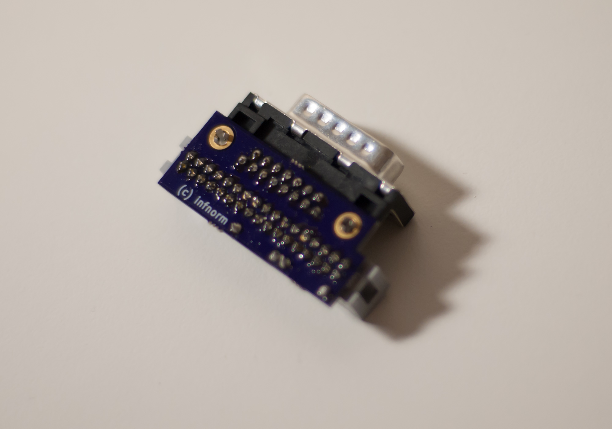
 It looked awesome, and the Apple IIgs RGB D-SUB connector also had arrived and fit nicely
 Unfortunately, the ribbon cable connector did not fit, because I had used the wrong hole size. The holes were too small. This was really frustrating, and it is exactly why I generally hate the idea of manufactured boards. It is too damn easy to waste your money! I didn’t really think I could drill the holes out to fix it, because there wasn’t really that much clearance, and again, I don’t have a drill press (or CNC). I settled with myself that I should just get another run done for only $5 dollars, but before I do that, I wanted to make sure things worked.
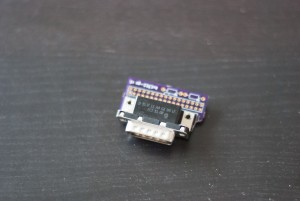
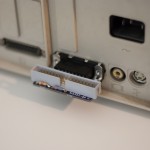
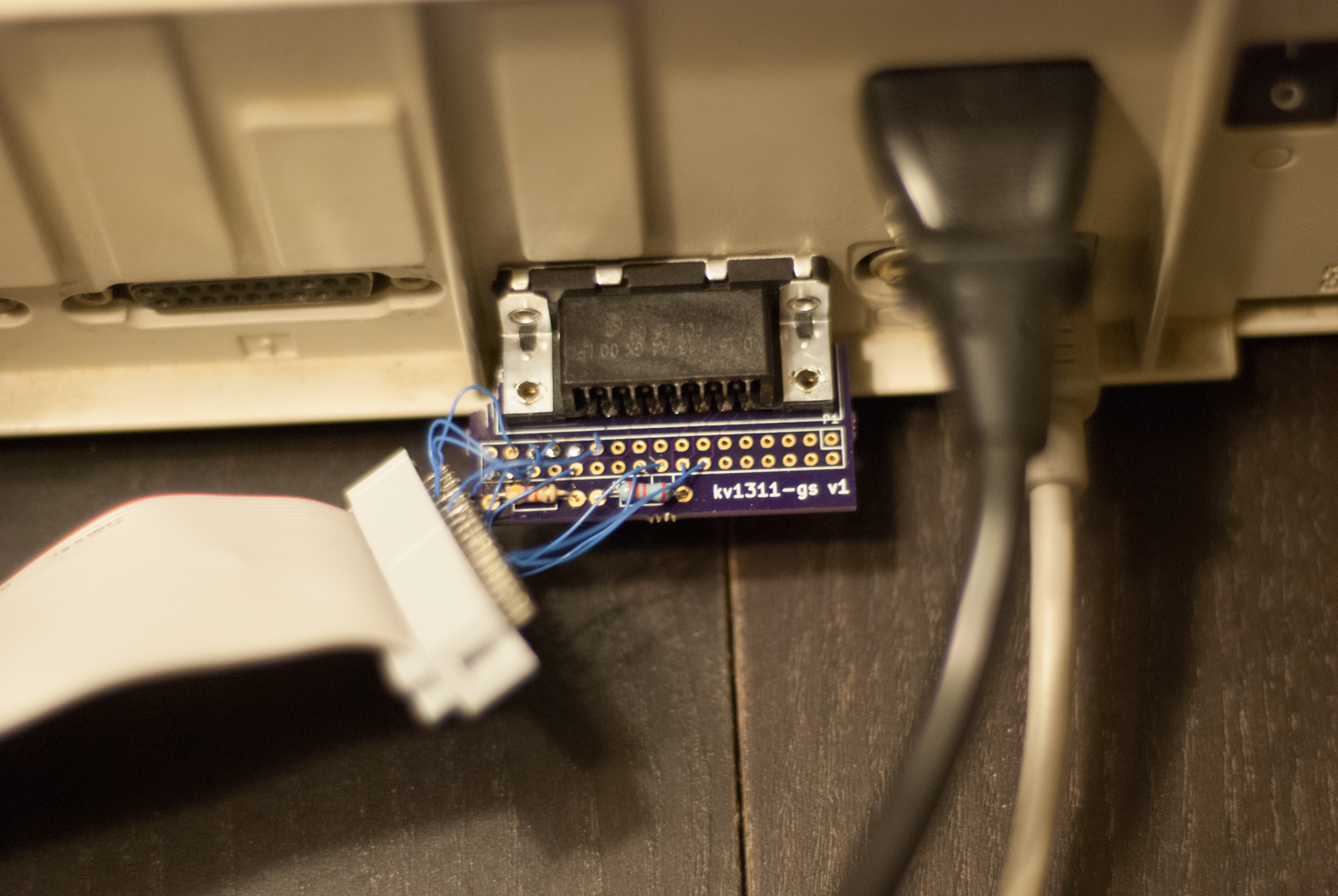
My solution was to wire wrap wires to the ribbon cable connector and solder those to the board. This sucked, but it wasn’t that bad, in that I decided I probably could get away with only 4 ground connections because there can’t be that much current…. 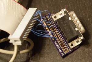 Yes. This is ugly. I also plan on throwing it away once I get new boards made. I had also made one more error. The board was a little too wide and bumped against part of the Apple IIgs case, so I needed to cut a notch out of the board like this:
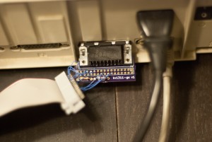
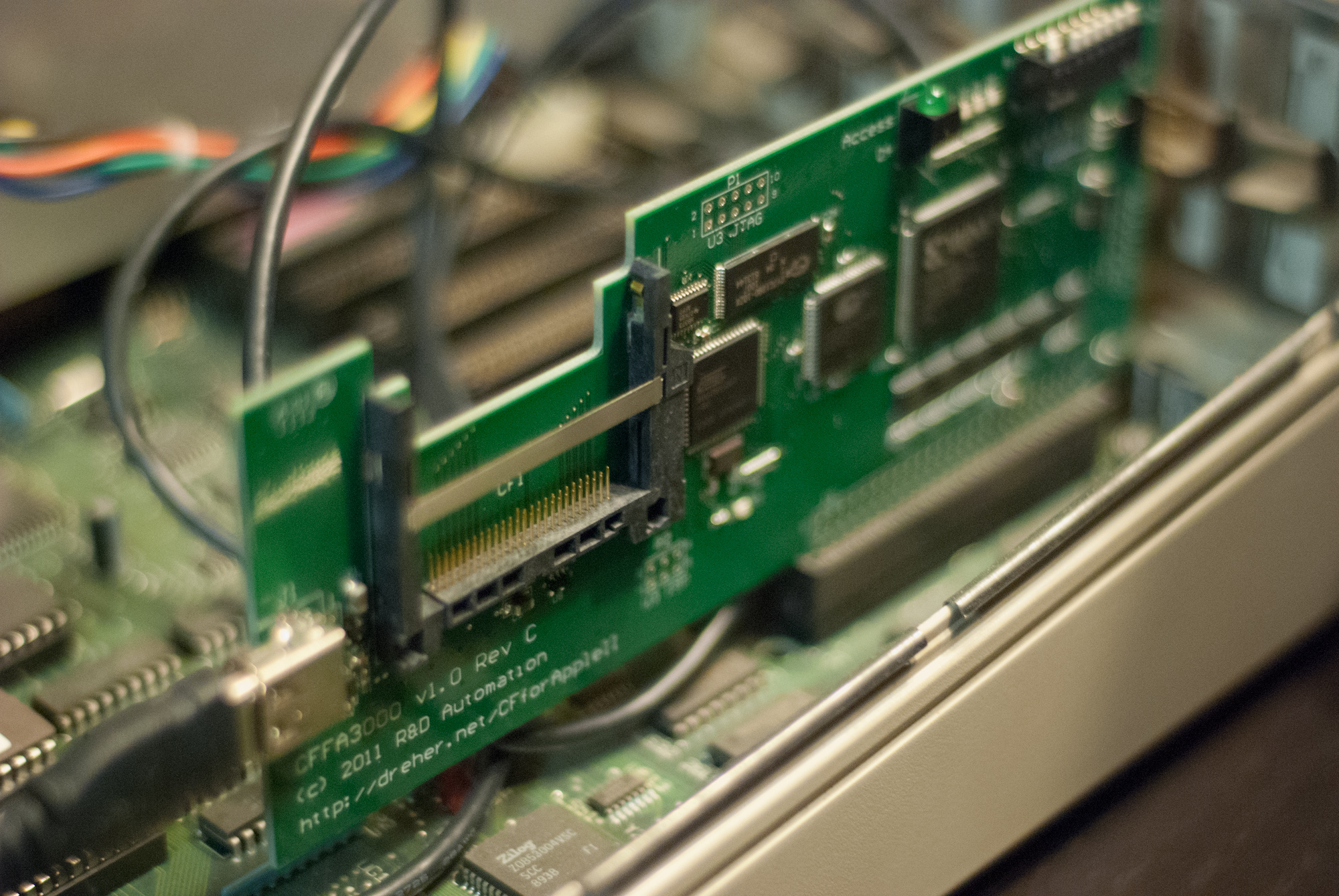
Once I did that things fit perfectly
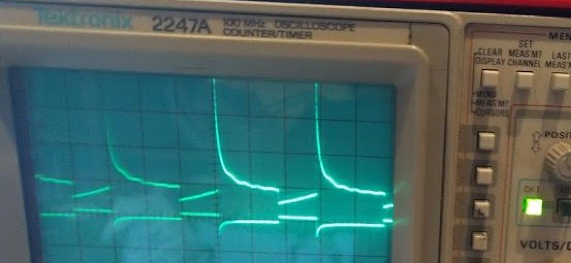
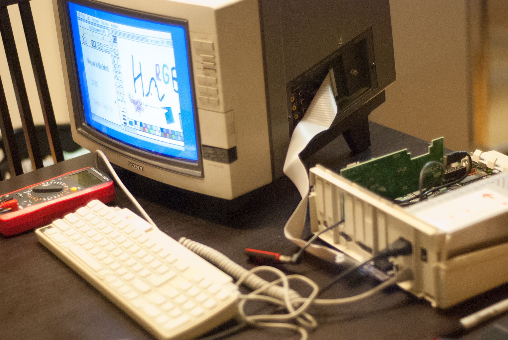
 Before I plugged this into my monitor I used my voltmeter to make sure I was driving the last two pins with 5V only and I used my oscilloscope to make sure I was getting the correct signals on the correct pins. Everything looked great so I plugged it in and wrote a simple basic program to look at some colors
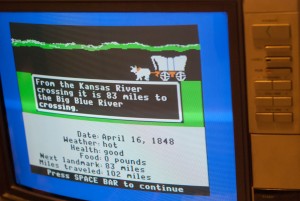
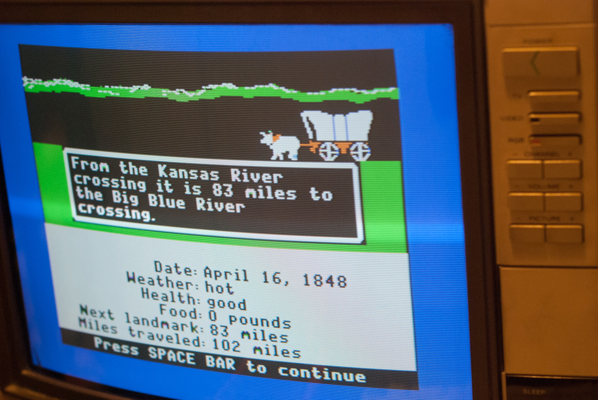
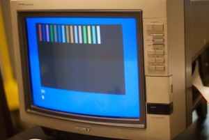 This is quite boring and doesn’t look as good in the photograph as it does in real life. Oregon trail happily works perfectly.
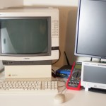
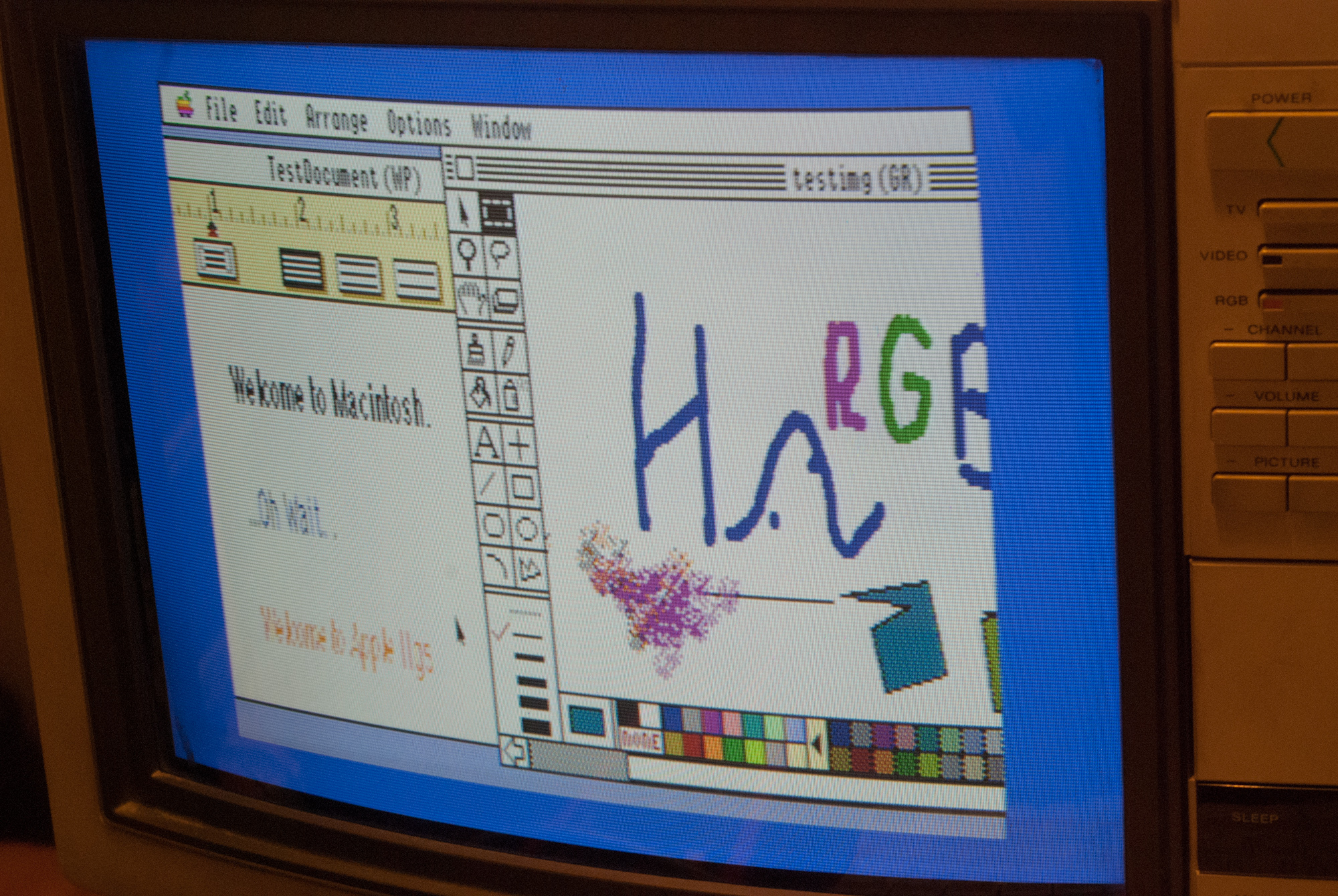
I also ran some of the mac-like Apple IIgs software like AppleWorks GS

It looks incredible and I am quite happy.
 �
�
Conclusion
So where does this all leave me. I made a working cable, but I need to edit my design and get new boards manufactured. Then I need to design an enclosure for the conversion PCB. I am quite happy with this way of making custom cables, and I might use it in the future for other similar tasks. I am sticking with KiCad for the long hall, though I might try Altium’s new tool just for fun. Using OSHpark was quite nice, and I will definitely use it again for small boards. For larger boards, I am inclined to try Elecrow, but we will see. I am also still inclined to make boards at home for prototyping, though if I am going to do anymore, I’m going to get a dremmel drill press jig, because my hands are not as steady as blondihack’s.
As far as my Apple IIgs. On the one hand, using this RGB monitor is still temporary, because it could easily fail, because all CRTs seem to be dropping dead. When that happens I can try my hand at learning CRT repair (e.g. recapping). Or, I can make a scan doubler at that point. Either way, I’m happy for now.
I need to make a custom stand to hold the monitor above the Apple IIgs, because the IIgs cannot safely support the larger KV-1311CR monitor. I would also like to find some solution for connecting the IIgs to the internet. I am thinking that PPP over a serial port is the most practical solution, but I haven’t looked into it carefully yet.


 U
U
