As I’ve been trying to learn more about electronics, circuit simulation is an interesting route to go. No messy wires, can easily see idealized properties on a virtual oscilloscope, don’t have to wait for parts. Obviously there are limitations to models and nothing beats getting the real thing to work.
There are many SPICE derivatives that one can select. Perhaps the easiest to use is LTspice. The main innovation in the original spice paper was a practical bipolar transistor model that was suitable for simulation. The basic technique of SPICE varies based on what type of simulation. Currently I am interested in the transient analysis which gives a time varying definition of the voltage and current for any point in the circuit. There are other modes and even the simplest operating point analysis (tutorial on the eevblog) is powerful.
The project
SPICE is nice and all, but since I want to learn how things work, I thought I’d write a circuit simulator from scratch in JavaScript. It shouldn’t be that hard, and it should really hone my intuition about how circuits work in a way that is much funner than solving basic circuits. Ideally I’ll do this in phases. For the first version described here I’ll support
- Ideal voltage sources
- Manual hard-coded circuits in the javascript file
- Resistors and capacitors (linear passives)
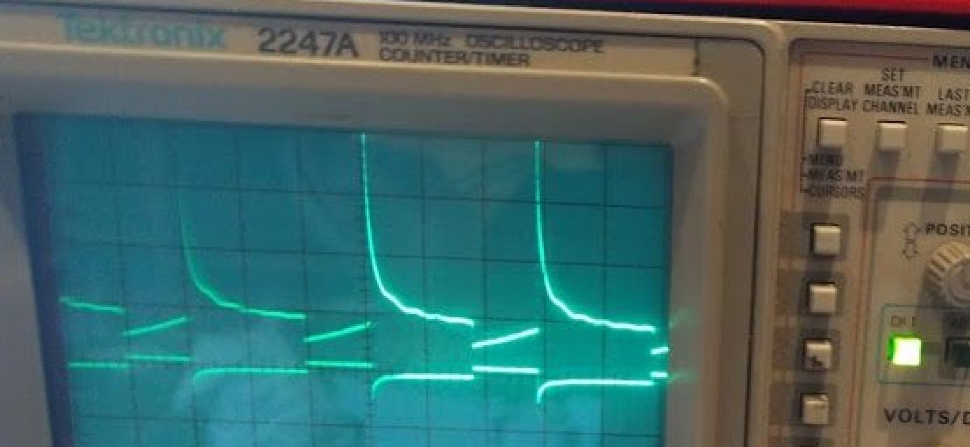
- Oscilloscope like view
In a later version these features would be nice to have
- Inductors and diodes (non-linear passives)
- Ideal opamps
- Transistors and FETs
- Transformers
Theory on solving circuits
The basic method we are going to use is Kirchoff’s Current Law that states that the net incoming and outgoing current is zero. So, basically for any component that has k nodes, it will contribute to k KCL equations in the circuit. Basically we need to solve all of the KCL simultaneously, so this should basically imply we are solving a big matrix. So let’s do a simple circuit example:

Notice how I have specified a GND to the circuit. This is essential, if you don’t do this you can’t solve for voltages because they won’t be relative to any zero. Now that we have our circuit, we need to write the KCL laws for all the nodes which will form some of the constraints of our circuit solution.
Let’s denote voltage at A, B, GND to be v(A), v(B), v(GND), respectively. The KCL at B is clearly -v(B)}{100} - \frac{v(B)-v(GND)}{100} = 0")
Now the slightly tricky part, writing the KCL laws for GND and A, because we don’t directly know the current going through V1. There is no Ohm’s law to help us here. Probably I should have started this endeavear with current sources, but let’s just go with it. The major observation is that we need to introduce an unknown variable for the current through V1, we’ll call it i(V1). That gives us  - \frac{v(A)-v(B)}{100} = 0")
Next we should write KCL for the GND node. However, that really wouldn’t be particularly interesting, because we already know what v(GND) will be — zero. So we will use =0")
So now we have three equations but four unknowns v(A),v(B),v(G),i(V1). We need one more equation to have a fully determined linear system,. One fact we haven’t included is that the voltage between A and G should be 5. So that gives us -v(G)-5=0")
-v(B)}{100} - \frac{v(B)-v(G)}{100} & = & 0 \\ v(G) & = & 0 \\ i(V1) - \frac{v(A)-v(B)}{100} & = & 0 \\ v(A)-v(G) - 5 & = & 0 \end{matrix}")
We can rewrite this in matrix form (Ax=b) and we get

The rows can be reordered to reflect the symmetry better.

If we plug this into our favorite linear solver (in this case I’m using SAGE)
from numpy import arange, eye, linalg
a=1/100;
A=matrix([[-a,a,0,1],[a,-2*a,a,0],[0,0,1,0],[1,0,-1,0]]);
b=matrix([[0],[0],[0],[5]]);
linalg.solve(A,b)
array([[ 5.   ],
       [ 2.5  ],
       [ 0.   ],
       [ 0.025]])
In other words v(A)=5 volts, v(B)=2.5 volts (go voltage divider), v(G)=0 volts, i(V1)=0.025 A. Everything is as we expected. In the next part we see how to code this into something that doesn’t require all this manual effort.
Hi Andrew,
I am just learning javascript and plans to make the visualization of simple electric circuit. I think it really helped me to start.. Thank you very much!