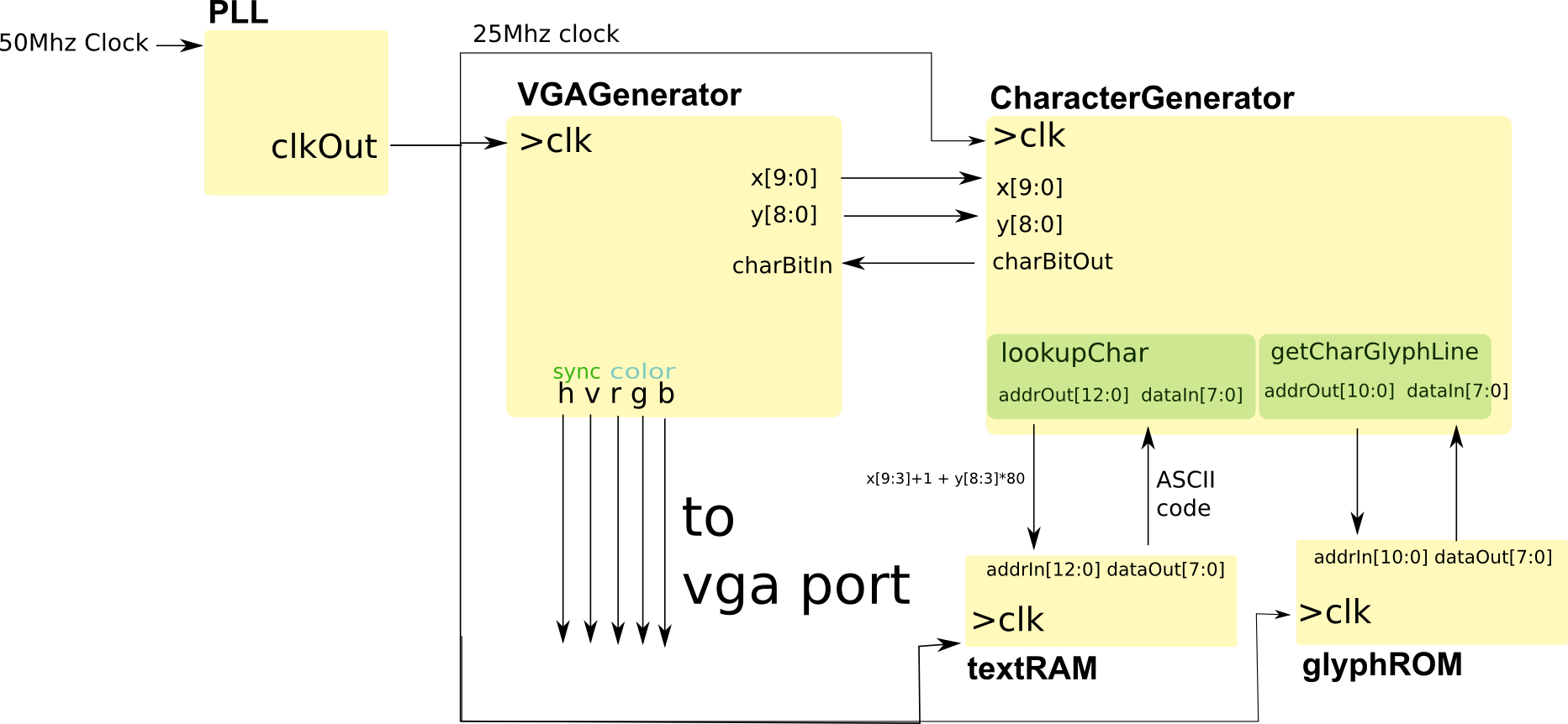
In the last post we got our FPGA up and running and started generating VGA signals and some simple test patterns. Today, we want to work on character generation so we can actually display text. We’ll need to make RAM to hold the character buffer (which will eventually be mutated by a CPU or some such thing). We’ll also need a ROM that stores the bitmap glyphs so that when we get an ASCII code from the the appropriate row and column, we can turn it into something that looks good. The basic block diagram for the approach is shown below:
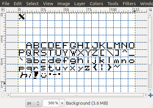
Before getting into the hardware programming of RAM and ROM (uncharted territory) I decided to do something easy. I fired up gimp and made a grid of 8×8 characters and started drawing characters. They are crappy, but they are mine.
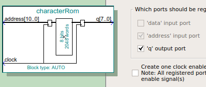
All good and fine, but I now need to turn this into a ROM. There are lots of ways of doing this, but since I am using the Altera FPGA tools I use the single port megafunction. This is nice and all, but it basically forces me to use some weird format for the binary data. I have a choice of two and I decide to use intel hex, because I found a python library that can generate then. Now I need to convert my font to .hex, so I write a python script that does this. I followed a similar approach to make a RAM.
Now back to the hardware design. I’ll freely admit that I struggle trying to minimize the use of registers and try to use as much stuff that will synthesize into combinatorial logic rather than sequential. In fact, the character generator itself was a lot trickier than I expected. I ran into several problems.
First, I needed to change my VGA generation logic so that x was not completely invalid before getting into the active display region (non-blanking time). Specifically I needed to be able to compute the notion of “nextColumn” even before I was in a valid x coordinate. The easiest way I could think to do this was to initialize x to be 1024-8 (8 ints before it overflows). That way when I add to compute the “next x” I will get 0 when I am about to enter the active region. This sounds weird and stupid, and maybe it is, but it was essential and worked fine. The “next” column of the character buffer (the one we need to load).
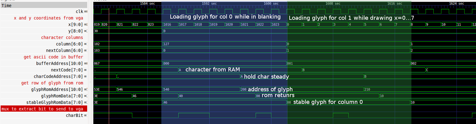
Second, I needed to be very careful about the timing. The idea is that each column of text takes 8 clocks to draw. I need a register that holds one line of the character glyph steady for those 8 clocks (using a mux to choose which bit of the register to use). I basically can use the 8 clocks however I see fit. There are unfortunately some extra registers holding the address in the Altera FPGA mega structures (more on that later). That would be fine if they were controllable (i.e. if they had an enable bit). Instead, I have to make my own address registers which delays things one clock. Annoying. You can sort of see the dance of how things work in my annotated timing diagram below. I generated this by simulating using icarus verilog. That required me to make a fake RAM and ROM to replace the Altera mega functions, but that was a good exercise.
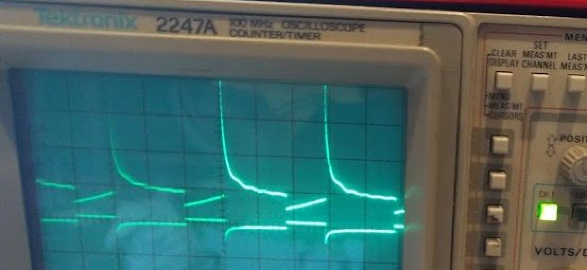
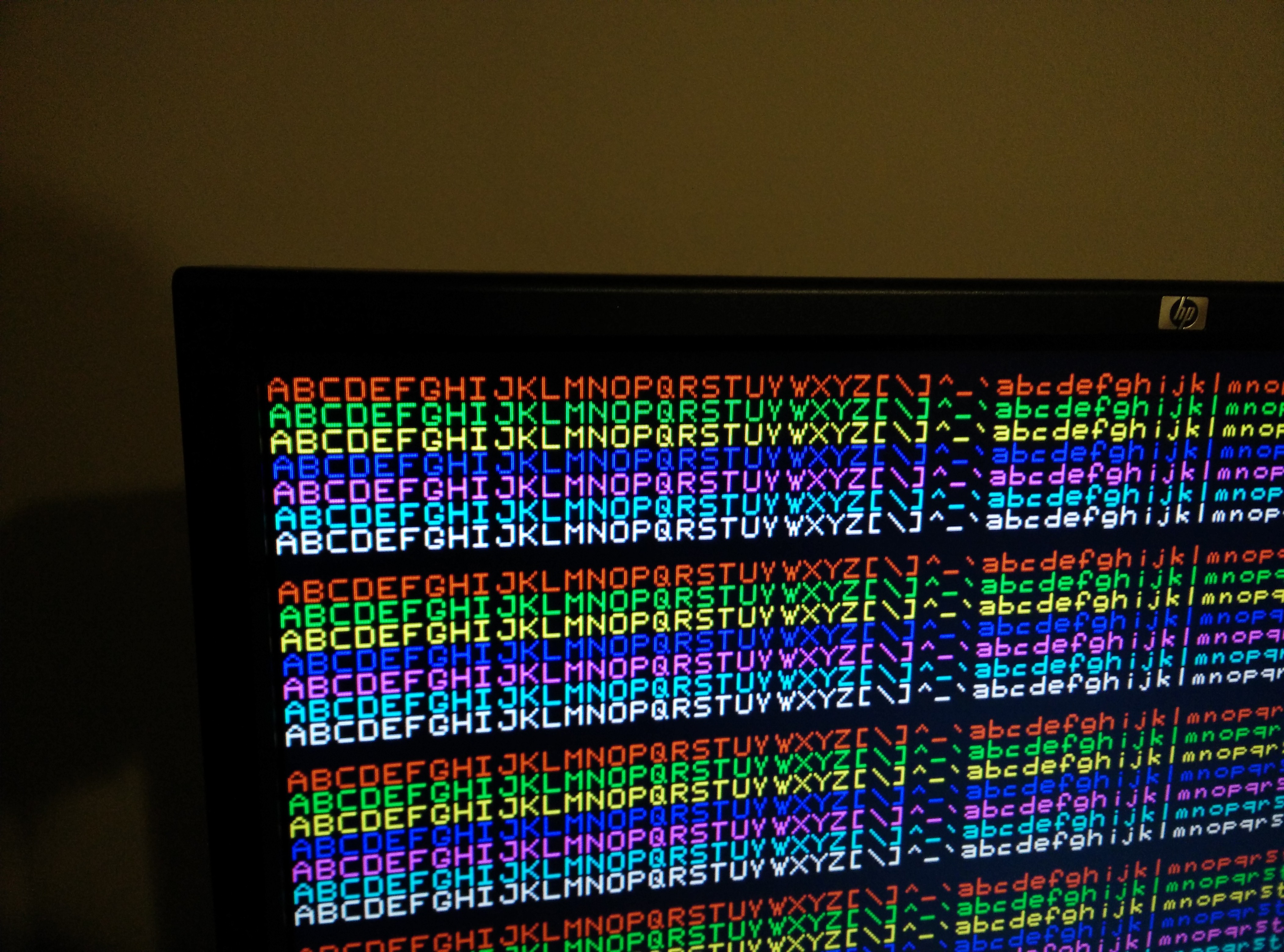
Before I carefully sat down to think about the timing, I was getting all kinds of artifacts like the one shown below:

I found a major cause of these kinds of problems was that in my generation of the RAM and ROM’s with the Quartus wizards, I had kept many default settings. One default setting is to have an extra register on the output of the RAM/ROM. This delayed the timing one more clock for no good reason. See the annoying setting below:
 vs.
vs. 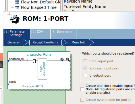
Unchecking that made things work better!
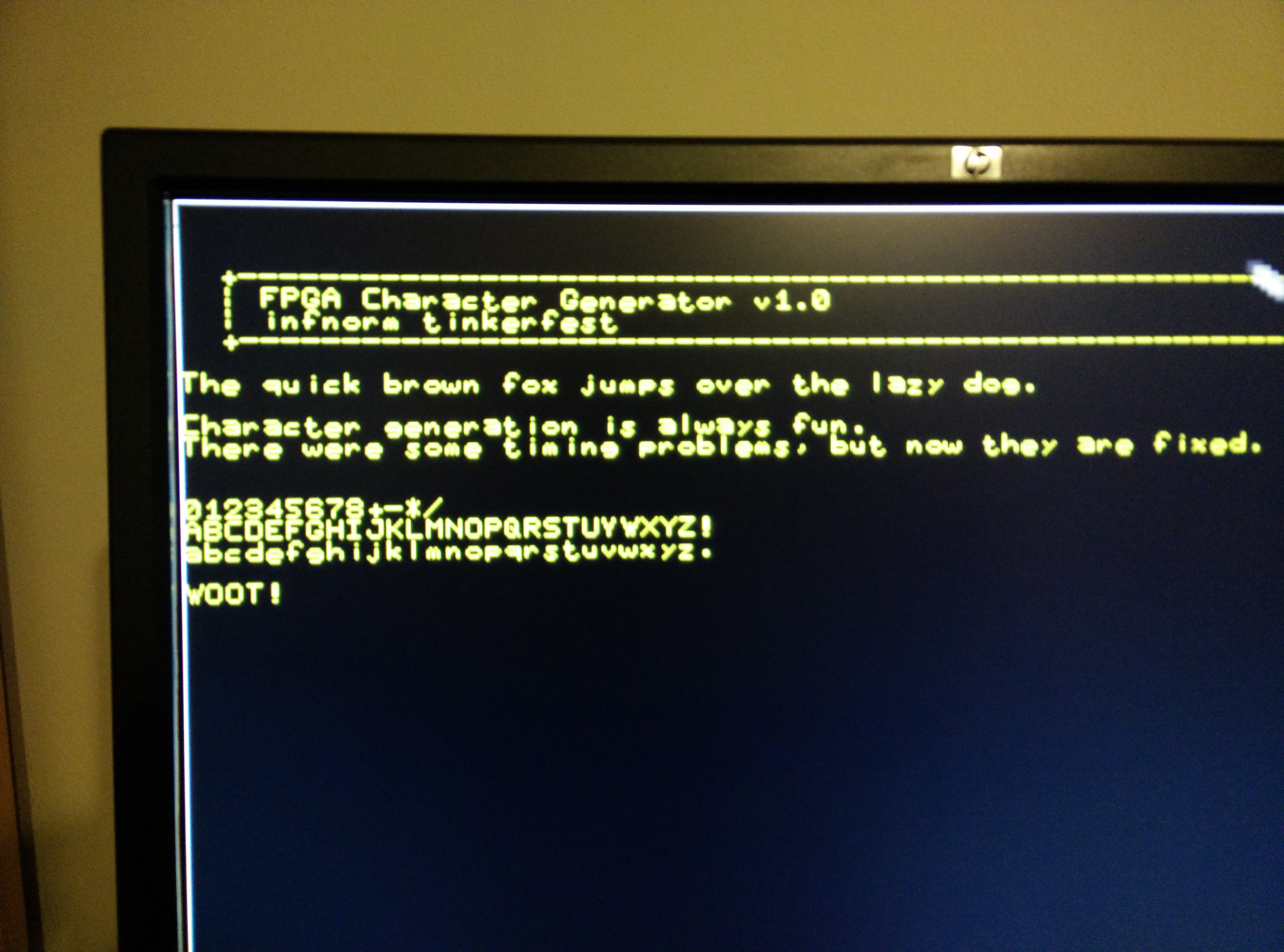
At the end of all this I decided to make a simple white instead of cheesy rainbow colors. I also made a slightly more interesting message:
I don’t know where I am going to go from here. An obvious thing to do would be to interface with a PS/2 keyboard or a serial port. If I did both I could make a simple dumb terminal. That could be kind of cool. Another cool thing to try would be to try to make a larger framebuffer (probably using external static ram) so I can do more interesting graphics. I might even add more rungs to my resistor DAC so I can get arbitrary colors. I could then implement a simple RAMDAC in the FPGA.
Thanks for mentioning the extra register on output q. This helped me fix a similar problem I was having.
Glad it helped you!
Do you have the codes?
Hi,
how are you doing?.. hope every thing is ok. i am just wondering if there are any tutorials about VGA. i wanna learn about it from the beginning until making some circuits and codes to controlling texts. i will be waiting for your answer at my Eamil :).
thank you,