The impetus
I grew up with Apple IIs. My first home computer was an Apple IIc. While I had a love hate relationship with it, especially circa 1991-1992 when I wanted to have a “modern” PC or Mac at home instead of the very limited 6502 based system. Every now and then the nostalgia center of my brain sucks me toward Apple II emulators. Even so, the real thing is, well, cooler. My parents kept the Apple IIc and its excellent Apple composite color monitor, and one day, I will import that from Wisconsin to California (don’t tell my wife). Two years ago I acquired an Apple IIe and Apple IIgs from craigslist, and I was excited, because while I had used both machines back in the day, I had never owned them. I was especially excited about the Apple IIgs, because I wanted to try programming some of the Super hires graphics modes that I didn’t even know existed when I was programming basic (hell I didn’t even know that you could program double-hires).
Anyways, I brought those bad boys home and I got them running, transferred some disk images, and played around with them. Quickly two problems emerged: I didn’t really want to use floppies that much, and the scan converting box from my playstation 2 days was not going to cut it. 40 column and graphics was OK, but 80 column and Super Hires just sucked.
Ditching disks
The disk problem was the easier problem to solve. My dad brought me a back of 5 1/4″ disks and my favorite Apple II game Thunderchopper when he visited, so I was able to use ADT to bootstrap some disks. Not only were disks inconvenient. but I did not get a 3.5″ drive for my Apple IIgs, so I would be severely limited in what I could do with only a 5 1/4″. I really wanted a Flash solution. The internet told me there was a great option the CFFA3000 (or video demo). I decided to put myself on the waitlist, and eventually I got it. It is an extremely well engineered piece of awesomeness, works perfectly, does everything I would want (except remote loading over ethernet). Here’s a picture of it in my IIgs.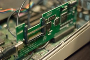
I will remark that it is quite excellent in the IIgs where you can switch disks with Apple-option-escape, but it is a little clunky to use in an Apple IIe. This of course is not a workable solution in the Apple IIc where there are no expansion ports. Recently BMOW has been developing firmware to emulate floppy drives using the standard floppy connector. This is quite excellent too, but I am very happy with the CFFA 3000 right now.
Searching for a display
The search is not helped by the problem that RGB monitors in the mid-eighties were all slow-scan i.e. 15kHz rather than 31kHz. Most modern VGA monitors cannot sync to lower than 31kHz nowadays. You can use a scan doubler like NTSC TV signals can be scan-doubled in order to use them with a VGA display. There is also the question of CRT vs LCD. I thought I would never own another CRT again after ditching my ViewSonic CRT that didn’t withstand the UPS “fragile” shipping.
I needed something better. Basically, doing a ton of research on the internets led me to these possibilities
- Find a 15khz monitor (AppleIIgs RGB, Amiga, Atari ST, Arcade CGA monitors could all work), but they are hard to find, expensive, and hard to ship.
- Scan doublers like GBS-8220 can work, but are not considered very high quality.
- Back in the day a VGA card for the Apple IIgs was created called the Secondsight, but it is rare and not fully compatible.
- Early multisync VGA montiors do support 15 kHz, but they are very hard to find.
- There are some LCDs that have SCART in the US, that work decently, but they are expensive and hard to find.
Needless to say, I was super discouraged at this point. I could throw money at the problem and buy a CRT, but it felt like a temporary solution. I was leaning toward the scan doubler approach, either building my own using an FPGA or using the GBS-8220. But, I didn’t have time so I put the project aside.
A plan forms
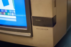
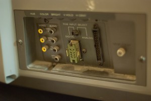
I was visiting my parents, and I realized they had a capable RGB monitor from the mid-eighties a Sony Trinitron KV-1311CR. This monitor was really quite nice in that had RGB, Composite and a cable tuner. In fact, I had used it in college as a television in my dorm room. The only problem was that it has this crazy RGB connector, a 34 pin ribbon DIP ribbon connector. (It also has that green RGB connector for digital (i.e. 8 colors) CGA displays).
So, I just needed to find the pinout for this monitor and the Apple IIgs RGB port and make a converter. This turned out relatively easy because it turns out “Don Lancaster’s Hardware Hacker” has an article on alternative RGB monitors for the Apple IIgs, and he has a diagram. He further says it’s an excellent monitor:
“The real winner seems to the be the great Sony KV-1311-CR monitor receiver. The praise lavished on this machine by the helpline callers was enough for me to actually go out and buy one for review and test.”
The big problem with using this monitor was getting it back to California intact. Moving CRTs requires lots of careful packaging. I used foam to pad the display, lots of bubble wrap before putting it into the box. Then I put that box in another box that was filled snugly with rolled up newspaper pages. Interestingly, the cheapest shipping option turned out to be checking it in my luggage (it cost only $35 (the price of an extra bag). Amazingly, it made it intact and working, though it looks like it was opened and searched (must be an uncommon item)/
The other big thing that I was concerned about was the pin numbering on the connector. I was concerned about how the pins were numbered on the ribbon connector. After scratching my head, the simplest way to figure it out was to find where the ground pins were (which I guess experienced people would say, duh, but hey I’m just a CS guy). So I just put my multimeter’s ground terminal onto the composite jack’s ground and found them. It turned out all the grounds were on one row (not the whole row, but almost). I can’t stress enough how frustrating this part was (doesn’t help to do this late at night). In fact, the numbering of the pins goes through one whole row and then to the other. This is different than an IDE which numbers swapping rows every pin number. I wanted to be absolutely sure, because I didn’t want to destroy a rare antique monitor by being careless.
The build
I have made cables many many times before. In fact, the first cable I made was an serial modem cable from Apple IIc DIN connector to IBM PC 9-pin connector to backup disks with ADT back in the 90’s. That cable was simply horrible (I didn’t even solder the wires because I didn’t have an iron or know how to solder). However, it did work. For this I wanted to do something a little more elegant. I figured I would create a PCB that had a male ribbon cable connector and the 15 pin male connector for the Apple IIgs side. Then, I can use a ribbon cable to connect to the monitor. If I get really clever, I could make a custom 3D printed cable housing for this. Doing a PCB for this does seem a little overkill, but it is not that crazy, considering OSHpark can produce boards dirt cheap, and I would need to find parts to make the hacked cable from anyways, why not do it right?
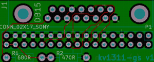
I’ve been using KiCad instead of eagle lately. Its routing is simply awesome compared to Eagle, but getting it setup is a real pain. Even so, I am very happy with it. Here is the basic schematic for the pinout. I really like making a schematic like this, because now I have documentation of how the cable works that I can share and refer to if anything goes wrong.
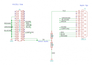 I quadruple checked all the connections. A neat factoid here is that both the Apple RGB connector and the sony have a pin for audio, so I decided to include that. Pin 33 enabled analog RGB (rather than IBM CGA style TTL RGB). Pin 34 enables audio. The resistors in the divider here are not important, and in my implementation I used a 3k3 and 2k instead of 680 and 470. You just need to generate 5 volts. Ideally I would twist the signal specific GND’s, but I didn’t do that and it worked fine (see below).
The Build
Once I had designed the schematic I checked everything again, and I made footprints for the schematic symbols (I think how KiCad does this makes a lot of sense rather than the eagle method). This is where I made a mistake :(, but we’ll get to that in a second. Here is the completed route which was quite easy to do with the push and shove routing!
and here is the for-free 3D model that KiCad produces. One day I need to learn how to model things in Wings3D so I can see populated board previews.
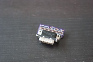
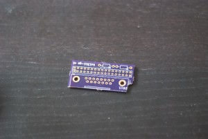
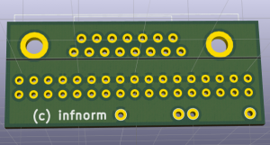 Now it was time to produce the board. This only requires one side, so I could easily etch it myself, but I have to get a drill press, and my VGA board was ruined twice by my inability to drill accurate holes. Doing dozens of pins that have to be exactly straight and aligned is really hard. Also, this board is really small, so it would only cost $5 to make with OSHpark. Furthermore, I was going on vacation to Utah for two weeks, so I was not in a hurry. So I sent it off before I went on vacation. When I got back, it had arrived and it looked like this
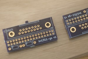 It looked awesome, and the Apple IIgs RGB D-SUB connector also had arrived and fit nicely
 Unfortunately, the ribbon cable connector did not fit, because I had used the wrong hole size. The holes were too small. This was really frustrating, and it is exactly why I generally hate the idea of manufactured boards. It is too damn easy to waste your money! I didn’t really think I could drill the holes out to fix it, because there wasn’t really that much clearance, and again, I don’t have a drill press (or CNC). I settled with myself that I should just get another run done for only $5 dollars, but before I do that, I wanted to make sure things worked.
My solution was to wire wrap wires to the ribbon cable connector and solder those to the board. This sucked, but it wasn’t that bad, in that I decided I probably could get away with only 4 ground connections because there can’t be that much current…. 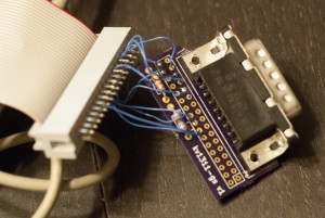 Yes. This is ugly. I also plan on throwing it away once I get new boards made. I had also made one more error. The board was a little too wide and bumped against part of the Apple IIgs case, so I needed to cut a notch out of the board like this:
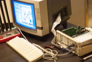
Once I did that things fit perfectly
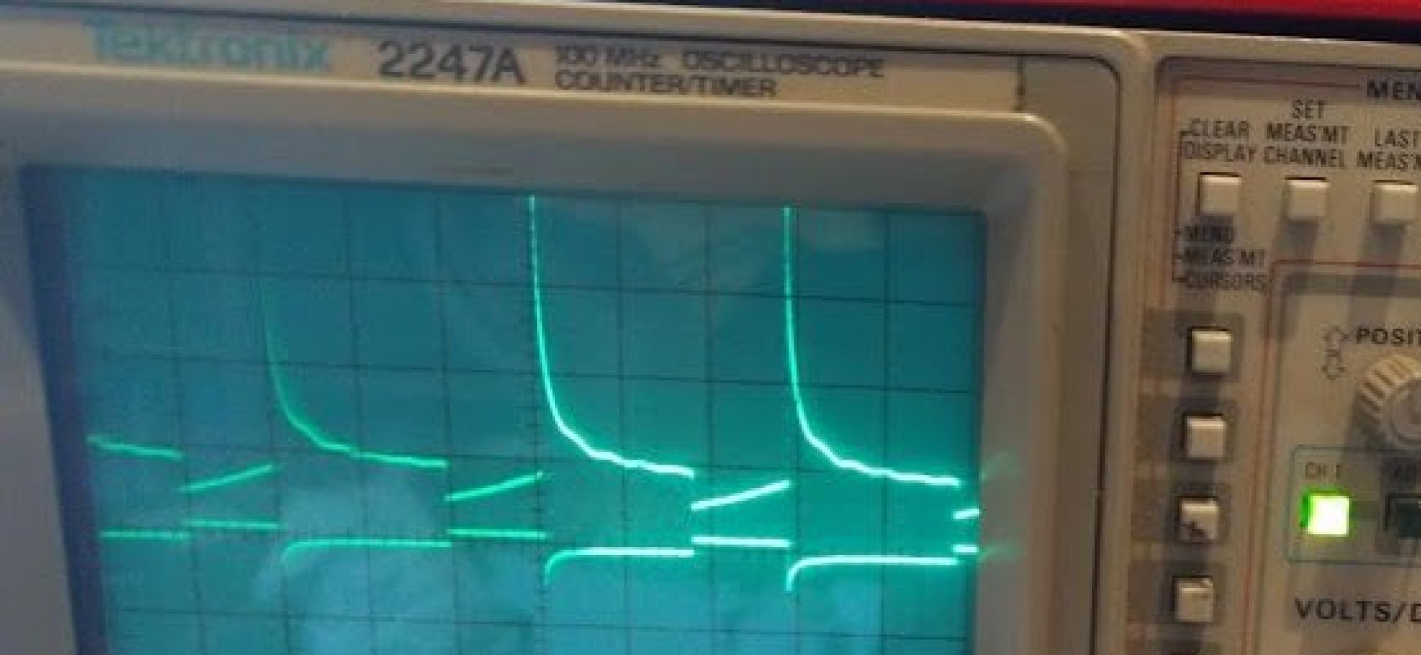
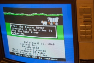
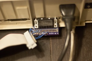 Before I plugged this into my monitor I used my voltmeter to make sure I was driving the last two pins with 5V only and I used my oscilloscope to make sure I was getting the correct signals on the correct pins. Everything looked great so I plugged it in and wrote a simple basic program to look at some colors
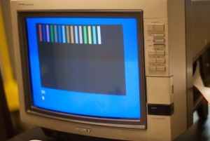 This is quite boring and doesn’t look as good in the photograph as it does in real life. Oregon trail happily works perfectly.
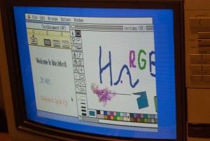
I also ran some of the mac-like Apple IIgs software like AppleWorks GS
It looks incredible and I am quite happy.
Conclusion
So where does this all leave me. I made a working cable, but I need to edit my design and get new boards manufactured. Then I need to design an enclosure for the conversion PCB. I am quite happy with this way of making custom cables, and I might use it in the future for other similar tasks. I am sticking with KiCad for the long hall, though I might try Altium’s new tool just for fun. Using OSHpark was quite nice, and I will definitely use it again for small boards. For larger boards, I am inclined to try Elecrow, but we will see. I am also still inclined to make boards at home for prototyping, though if I am going to do anymore, I’m going to get a dremmel drill press jig, because my hands are not as steady as blondihack’s.
As far as my Apple IIgs. On the one hand, using this RGB monitor is still temporary, because it could easily fail, because all CRTs seem to be dropping dead. When that happens I can try my hand at learning CRT repair (e.g. recapping). Or, I can make a scan doubler at that point. Either way, I’m happy for now.
I need to make a custom stand to hold the monitor above the Apple IIgs, because the IIgs cannot safely support the larger KV-1311CR monitor. I would also like to find some solution for connecting the IIgs to the internet. I am thinking that PPP over a serial port is the most practical solution, but I haven’t looked into it carefully yet.
What about the Apple II Workstation Card as a possible solution to the networking question?
That’s a good suggestion that I had not considered. I’ll have to see how easy they are to acquire. My understanding is they expose Appletalk, so I’d need to have a mac that has both appletalk and ethernet to act as a router. By contrast, if I use PPP/SLIP I can do it from any modern computer with a serial port. But it is definitely worth entertaining.
You don’t need an Apple II workstation card for the IIgs, Appletalk is built in (the workstation card is for the //e). Just change slot 2 in the control panel to “your card”, and slot 7 to “Appletalk”, then connect the Appletalk connection to the modem serial port (not the printer one). This does mean your CFFA-3000 card would have to be moved out of Slot 7, or it would be inaccessible while using Appletalk.
With the proper setup, it will boot from an Appleshare server without even any floppy drives connected!
Hey, good work on using the 34 pin proprietary Sony connector to display analog RGB. I want to do the exact same thing, except instead of hooking it up to a DB 15 connector I want to connect it to a female scart connector, so I can hook up RGB modded game consoles to it. Would you be interested in helping me make an adapter like this? I have already decided to go with a floppy style 34 conductor ribbon cable and attached it to a double row 17 pole header soldered onto a strip board. Now I just need to figure out all of the connections going to the female scart connector. If you are interested let me know, I will make it worth your while.
That sounds like a good idea. At some point in the future I’d like to do something similar for my Super Nintendo. I would love to help, but I am going to be quite busy with work for the next several months. 🙁
No problem, just thought I would check.
You could use a Jamma Board for VGA. I bought one for my IIgs, but haven’t hooked it up yet. It is basically a vga converter that takes in a plethora of different signals. It is designed to allow replacing arcade monitors with VGA. I’m using one on my Coleco Adam (it handles composite just as well as RGBA). I do still have my original IIgs monitor and use it with a CoCo 3. I have taken it a step further and connected the Jamma Board VGA output to an HDMI converter. All in all, the whole setup was less than $75 off the eBay from various sellers.
Thanks for the post. That’s a great suggestion as well.
Did you ever make another board at OSH park? I have the same monitor and just stumbled onto your site. Why re-invent the wheel. If you have a spare board (They always do 3) or if you have shared your project on OSH park that would be great too..
I happened across an NEC CM-2591A at a school garage sale that has the same 34-pin input. I want to use this RGB monitor in my retro gaming setup, but I can’t find anyone who can make the cable for it…
Hey great article, trying to find a replacement for my ailing IIGS RGB monitor, but just wanted to let you know your blog has been hacked. There is a link titled “acheter pharmacie viagra” right after this line above: “I was visiting my parents, and I realized they had a capable RGB monitor from the mid-eighties a Sony Trinitron KV-1311CR”
Thanks for the comment and the heads up.
Thanks for the heads up